Processor Board Component Locations
Processor Board Component Locations
A layout of the processor board is shown in the following illustration.
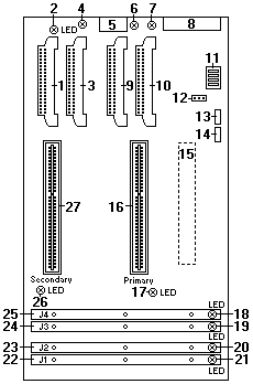
1 Secondary microprocessor cache VRM connector (U15)
2 Secondary microprocessor cache VRM error LED (CR36)
3 Secondary microprocessor core VRM connector (U7)
4 Secondary microprocessor core VRM error LED (CR37)
5 Power control connector (J17)
6 Primary microprocessor cache VRM error LED (CR19)
7 Primary microprocessor core VRM error LED (CR17)
8 Power supply connector (J10)
9 Primary microprocessor cache VRM connector (U17)
10 Primary microprocessor core VRM connector (U22)
11 Microprocessor core-ratio-selection switch block (SW1)
12 Reserved (J22)
13 Reserved (J20)
14 Reserved (J18)
15 System board connector (J9) (on reverse side of processor board)
16 Primary microprocessor connector (U5)
17 Primary microprocessor error LED (CR12)
18 DIMM 1 error LED (CR8)
19 DIMM 2 error LED (CR9)
20 DIMM 3 error LED (CR10)
21 DIMM 4 error LED (CR11)
22 DIMM socket 4 (J1)
23 DIMM socket 3 (J2)
24 DIMM socket 2 (J3)
25 DIMM socket 1 (J4)
26 Secondary microprocessor error LED (CR13)
27 Secondary microprocessor connector (U6)
Back to 
Please see the LEGAL - Trademark notice.
Feel free - send a  for any BUG on this page found - Thank you.