Installing a Microprocessor Kit
Installing a Microprocessor Kit
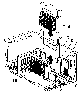
Refer to the following illustrations of the processor
assembly and processor board while you perform the steps
in this procedure:

1 Processor assembly top cover
2 Quarter-turn fasteners

3 Latches
4 Secondary microprocessor
5 Terminator card
6 Secondary microprocessor connector
7 Voltage regulator modules (VRMs) for secondary microprocessor
8 VRM connectors for secondary microprocessor
9 VRMs for primary microprocessor
10 Primary microprocessor
Complete this procedure to install a microprocessor kit in
the processor assembly.
- Turn the quarter-turn fasteners 2 and remove the
processor assembly top cover 1.
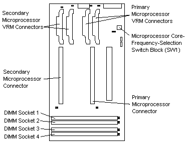
Refer to the processor board layout for component
locations.

- Install the microprocessor in the primary microprocessor connector.
- Touch the static-protective package containing
the new microprocessor to any unpainted metal
surface on the server; then remove the microprocessor from the package.
- Hold the microprocessor 10 by the open
latches 3 and center the microprocessor over
the microprocessor connector.
- Make sure the microprocessor is oriented and aligned correctly.
- Insert the microprocessor into the guides until it
seats in the connector. Close the latches.
- Install the two VRMs (voltage regulator modules) 9
in the primary microprocessor VRM connectors.
- Center one VRM over the connector.
- Make sure the VRM is oriented and aligned correctly.
- Press the VRM into the connector until the VRM
latches snap into the locked position.
- Repeat this procedure to install the other VRM.
- If you are installing a second microprocessor kit, complete this procedure.
- Remove the terminator card 5 from the
secondary microprocessor connector 6.
- Refer to the procedure in step 2 and install the
secondary microprocessor 4.
- Refer to the procedure in step 3 and install the
two VRMs 7 in the secondary microprocessor VRM connectors 8.
- Set the microprocessor core-ratio-selection switch
(SW1) for the correct microprocessor core ratio. For example, if you have a
450 MHz microprocessor installed, be sure that the microprocessor
core-ratio-selection switch is set to a microprocessor
core ratio of 4.5 (450/100). Refer to the following table.
Note:
To turn a switch Off, press the switch on the side where the word off is printed.
To turn a switch On, press the switch on the side opposite of where the word off is printed.
| CPU Core Ratio |
SW1 Position 1 |
SW1 Position 2 |
SW1 Position 3 |
SW1 Position 4 |
| 4.0 |
On |
On |
On |
Off |
| 4.5 |
On |
Off |
On |
Off |
| 5.0 |
On |
On |
Off |
Off |
Back to 
Please see the LEGAL - Trademark notice.
Feel free - send a  for any BUG on this page found - Thank you.


![]()
 for any BUG on this page found - Thank you.