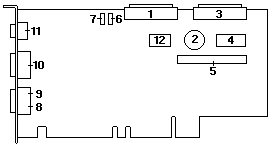
I/O Function Card Component Locations
The following simplified layout of the I/O function card identifies the components.
I/O Function Card Jumpers
Table 10 describes the jumpers on the I/O function card.
The highlighted numbers in the table correspond to the numbers
on the above adapter illustration.
Note: Turn off the server, and disconnect the power cord before moving any jumpers.
Table 10. I/O Board Jumpers
Please see the LEGAL - Trademark notice.
Jumper Name
Description
6 - J17 Power on
password overrideChanging the position of this jumper bypasses
the power-on password check. You do not
need to move the jumper back to the default
position after the password is overridden. To
do this:
1. Shut down and power-off the system.
2. Move jumper J17, then, power-on the
system. POST will clear the password.
Note:
Changing the position of this jumper
does not affect the administrator
password. If the administrator
password is set, you must replace the
I/O board.
7 - J16 Flash page swap
The default position is a jumper installed on
pins 2 and 3. Changing the position of this
jumper will change which of the two pages of
flash ROM is used when the system is
started. You can use this jumper to recover
from a BIOS flash update problem. To do
this:
1. Power-off the system.
2. Move jumper J16, then, power-on the
system.
Back to ![]()
Feel free - send a  for any BUG on this page found - Thank you.