Input/Output Connectors and Expansion Slots Netfinity 7000-M10 - Type 8680
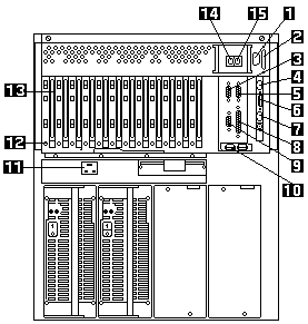
The following illustration shows the expansion slots and the input/output connectors
(ports) on the rear of the server.

2 - SCSI Connector: External SCSI devices attach here.
3 - Serial A Connector: Serial signal cables for modems and other serial devices connect here to
the 9-pin serial port A connector. See 'Devices and I/O Ports' for port assignment information.
If you are using a 25-pin signal cable, you need a 9-pin-to-25-pin adapter cable.
4 - 10/100 Ethernet Connector: This connector is to attach the Advanced Remote Management
Controller to a network hub for remote communication.
Note: The 10/100 Ethernet connector cannot be accessed from the network operating system.
The connector is dedicated to connecting the Advanced Remote Management Controller to an Ethernet network through a
service-processor interface, such as Netfinity Manager.
5 - Serial B Connector: Serial signal cables for modems and other serial devices connect here to
the 9-pin serial port B connector. See 'Devices and I/O Ports' for port assignment information.
If you are using a 25-pin signal cable, you need a 9-pin-to-25-pin adapter cable.
6 - Dual Serial Connector: This connector can be used to attach to a Y-cable that is shipped
with the server. This Y-cable can be used to attach to a modem that is dedicated to communication with the
Advanced Remote Management Controller.
7 - RS 485 Bus Connector: This connector is used to attach other compatible system management
adapters for remote access.
8 - Parallel Connector: A signal cable for a parallel device, such as a printer connects here.
9 - Video Connector: The monitor signal cable connects here.
10 - Universal Serial Bus Connectors: You can attach I/O devices to these two universal serial
bus (USB) connectors. You need a 4-pin cable to connect devices to USB 1 or 2.
A hot-plug keyboard-and-mouse option can be cabled or uncabled from the USB connectors without error or
loss of service.
Note: If a standard (non-USB) keyboard is attached to the keyboard port, the USB ports are
disabled while the power-on self-test (POST) is running and no USB devices will work during POST.
11 - Power Supply Connector: The system power cord connects here.
12 - Attention Lights for PCI Slots: Each PCI slot has an Attention light that is visible
from the rear of the server. An Attention light flashes approximately once per second when it is on.
The meaning of the Attention lights is defined by the operating system.
Refer to the operating-system documentation to determine if the operating system supports hot-plug
PCI adapters and, if so, what the Attention lights indicate.
13 - PCI Expansion Slots: The server has seven 32-bit and five 64-bit
peripheral component interconnect (PCI) expansion slots. All PCI slots support hot-plug PCI adapters.
You can install PCI adapters to provide communication, specialized graphics, and sound.
Many adapters provide bus-master capabilities, which enable the adapters to perform operations
without interrupting the system microprocessors.
14 - Keyboard Connector: The keyboard cable connects here.
15 - Mouse Connector: The mouse cable connects here.
This port sometimes is called an auxiliary-device or pointing-device port.
Note: For pin assignments and other details about these connectors, see 'Connecting External Options'.
Please see the LEGAL - Trademark notice.
Feel free - send a  for any BUG on this page found - Thank you.