Introducing SSA and RAID
This chapter describes:
Serial Storage Architecture (SSA)
Serial Storage Architecture (SSA) is an industry-standard interface
that provides high-performance fault-tolerant attachment ot I/O
storage devices. SSA is an open standard, and SSA specifications
have been approved by the SSA Industry Association and are in
the process of being approved as an ANSI standard through the ANSI
X3T1O.1 subcommittee.
In SSA subsystems, transmissions to several destinations are
multiplexed, the effective bandwidth is further increased by
spatial reuse of the individual links. Commands are forwarded
automatically from device to device along a loop until the target device is
reached. Multiple commands can be travelling around the loop
simultaneously.
SSA retains the SCSI-2 commands, queuing model, and status and
sense bytes.
SSA Loops and Links
In the simplest SSA configuration, SSA devices are connected
through two or more SSA links to an SSA adapter that is located
in the system unit. The devices, SSA links, and SSA adapter are
configured in loops. Each loop provides a data path that starts
at one connector of the SSA adapter and passes through a link (SSA
cable) to the devices. The loop continues through the devices,
then returns through another link to a second connector on the SSA
adapter.
The maximum permitted length for an external cable that connects
two SSA nodes (for example, disk drives) is 25 meters (82 feet).
Details of the rules for configuring SSA loops are given for
each SSA adapter in 'Rules for SSA Loops'.
Loops and Data Paths
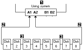
All devices that are attached to an SSA adapter card -1- are
connected through SSA links -2-. The SSA links are configured in
loops. Data and commands to a particular device pass through all
other devices on the link between the adapter and the target device.
Data can travel in either direction round a loop. The adapter
can, therefore, get access to the devices -3- (disk drives in this
example) through two data paths. The system cannot detect which data path
is being used.


Please see the LEGAL - Trademark notice.
Feel free - send a  for any BUG on this page found - Thank you.