Memory Board/Memory-Module Kits (Netfinity 7000 - 8651)
Memory Board/Memory-Module Kits
NOTE:
- The server uses 6Ons, 168-pin, error correction
code (FCC), dual inline memory modules (DIMMs).
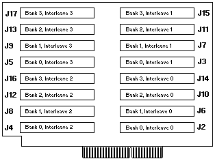
- The memory board contains four banks (0-3),
arranged in 16 DIMM connectors and supports
4-way memory interleaving.
- You can install a maximum of 4 GB of memory in
the server, with 256 MB memory modules in all
16 connectors (J2 through J17).
- Each bank contains connectors for four memory
modules. The memory-module kit sizes available
for the server are 64 MB, 128 MB, and 256MB.
- As a minimum, the server requires 1 full bank of memory.
- To ensure proper server operation, you must
maintain 4, 8, 12, or 16 memory modules in the server.
- All the DIMMs installed in a bank must be the
same size, but different banks can have different sized DIMMs.

Several examples of memory module configurations are:
- The base memory is four 64 MB DIMMs. The DIMMs
are installed in bank 0, connectors J2-J5.
- You want four 64 MB DIMMS, eight 128 MB DIMMs,
and four 256 MB DIMMs in the server.
Leave the 64 MB DIMMS in bank 0, connectors J2-J5 and install
the 128 MB DIMMS in bank 1, connectors J6-J9 and
bank 2 connectors J10-J13 and the 256 MB DIMMs in
banks, connectors J14-J17.
NOTE:
- Use DIMMs that are compatible with Joint
Electron Device Engineering Council (JEDEC) standards.
- The server does not support memory expansion adapters.

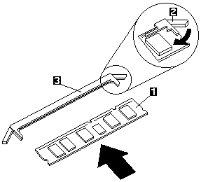
- Memory module (DIMM)
- Retaining clip
- Memory-module connector
To install the memory module:
- Place the memory board,. component-side up, on a
flat, static-protective surface.
- Locate the memory-module connectors on the
memory board.
- Touch the static-protective package containing the
memory-module kit to any unpainted metal surface on
the server. Then, remove the memory-module kit from the package.
- Install the kit:
 To avoid breaking the retaining clips or damaging
the memory-module connectors, handle the clips gently.
- Start with the lowest-numbered connectors (bank 0).
- Turn the memory module (DIMM) -1- so that the pins align correctly with the memory-board connector.
- Insert the DIMM into the memory-module connector -3- by pressing on one end of the
DIMM and then on the other end of the DIMM. Be sure to press straight into the connector.
- Repeat the preceding step to make sure the DIMM is seated correctly.
- Make sure the retaining clips are in the closed position.
- If a gap exists between the DIMM and the retaining clips -2-, the DIMM has not been
properly installed. In this case, open the retaining clips and remove the DIMM, then, reinsert the DIMM.
- Repeat these steps for each memory module that you install.
NOTE: To ensure proper server operation, you must
install memory modules in groups of four. All the memory modules installed in a bank
must be the same size, but difterent banks can have different sized memory modules installed.
- Reinstall the memory board and board-support panel.
 When you install the memory board in the server,
be sure that it is completely and correctly seated
in the system-board connector before you apply
power. (The latches on the boards will be
horizontal.) Incomplete insertion might cause
damage to the system board or the memory board.
Back to 
Please see the LEGAL - Trademark notice.
Feel free - send a  for any BUG on this page found - Thank you.


 To avoid breaking the retaining clips or damaging
the memory-module connectors, handle the clips gently.
 When you install the memory board in the server,
be sure that it is completely and correctly seated
in the system-board connector before you apply
power. (The latches on the boards will be
horizontal.) Incomplete insertion might cause
damage to the system board or the memory board.
 for any BUG on this page found - Thank you.