2140 Processor Card (750Ce, 755C, 755Cs)
2140 Processor Card (750Ce, 755C, 755Cs)

The system board can be damaged if the lower shield touches the
system board components.
Carefully follow the next instruction.
In step 3,
gradually raise the system board from the lower shield until all
components of the system board just clear the tabs of the
lower shield.
Be careful not to raise it too far.
While keeping the clearance to a minimum, separate the system board
from the lower shield by moving the system board
straight forward as shown by step 3
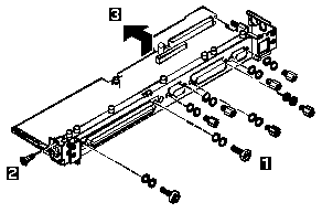
NOTE:
In step 1, each screw has
a flat washer and a lock washer.
When reinstalling the screws, make sure that the lock washer
is placed next to the head of the screw.
Incorrect washer placement can cause metal to flake.
Turn the system board upside down. Remove the screws
4 and 5.
Models 370C, 755C and 755Cs have only the screw on the right side
in step 5.
- In step 1, use 5.0 mm and 5.5 mm hex head screwdrivers.
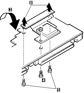
To remove the processor card, gently lift
the area shown by 3 straight up.
Do not pull the other areas.
- In step 6, pull both edges of the bracket at the same time.
Do not pull the center of the bracket.
Use the following table for reference when replacing parts.
| Step |
Location (Quantity) |
Length |
| 1 |
Expansion bus, lower shield (2) |
Hex head |
| 1 |
I/O connector, lower shield (6) |
Hex head |
| 4 |
Processor card (1) |
6 mm |
| 5 |
Processor card connector
750x - (2), 370C, 755C, 755Cs - (1) |
4 mm |
NOTE: Make sure you use the correct screw. Screw Size Chart
Back to 
Please see the LEGAL - Trademark notice.
Feel free - send a  for any BUG on this page found - Thank you.