When working with ENOVIA V5, the safe save mode ensures that you only create data in CATIA that can be correctly saved in ENOVIA V5.
ENOVIA V5 offers two different storage modes: Workpackage (Document kept - Publications Exposed) and Explode (Document not kept). Electrical products have been configured to work in both Workpackage mode and the Explode mode, depending on the objects considered.
This safe save mode means that certain commands are unavailable.
We recommend that you read the VPM Navigator User's
Guide to know more about this product.
This documentation can be found on the ENOVIA LifeCycle Applications
Documentation CDRom.
Working with Geometrical Bundle as Workpackage
![]()
A workpackage is one or more documents that are displayed
in ENOVIA V5 as a single entity.
This means that a node in the CATIA specification tree is chosen as an
entity to be shown in ENOVIA V5. The children are not visible as documents
in the ENOVIA V5 tree.
The geometrical bundle is a candidate to be stored this way, as it
represents a complete and coherent package for the electrical design.
![]()
If you are using Electrical Harness Flattening, it is the only mode supported to save geometrical bundle extracted data.
Within CATIA connected to ENOVIA V5 through VPM Navigator, if the user selects a new product as a geometrical bundle, the system automatically knows that this geometrical bundle has to be stored as a workpackage.
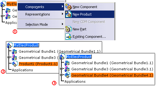
Checks are performed when using the Electrical tools to ensure that all entities created or modified will be correctly stored, using the following rules:
-
No links to geometry (that is to say external references) can be done from a part inside a workpackage to a part outside the workpackage.
Let's see an example:
With a geometrical bundle stored as a workpackage (publication exposed mode), the bundle segments belonging to this geometrical bundle cannot use, as routing objects, supports, devices or any geometry external to the geometrical bundle while keeping the contextuality. The external references won't be synchronized and the bundle segment shape won't any longer be contextual to any object outside the geometrical bundle. Contextual links are kept inside the geometrical bundle.
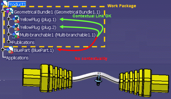
-
The context for the external links must be set to a product node inside the workpackage.
Refer to Infrastructure User's Guide - Customizing Part Infrastructure. -
Mechanical constraints and electrical connections between parts inside the workpackage and outside the workpackage must rely on published objects.
Bundle Segment-to-Support Link
As of Version 5 Release 16, you can manage links between bundle segments and supports when they are not in the same geometrical bundles. In particular, you can update bundle segments if supports, in a different geometrical bundle, have been moved.
For more information, see Updating Bundle Segment-to-Support Link.
- This functionality is applicable to electrical data created as of Version 5 Release 16 only. It does not support adaptive supports.
- The instance name of supports must be unique. The bundle segment-to-support link will not be updated if two or more instances have the same name in your session.
- Modifying the instance name will make the link invalid.
- Do not rename geometry created when routing bundle segments through supports.
Updating bundle segment-to-support links is based on a naming convention for support identifiers. Whenever a support is added, support geometry (published point and two published planes) is copied and renamed as follows:
Name of the geometry= [Instance name of selected
     support]![Name of the publication]
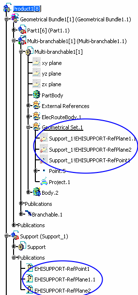
CATIA Settings
To make this possible, the following settings must be applied when working with CATIA connected to ENOVIA V5, to store the geometrical bundles as workpackage in ENOVIA V5:
![]()
-
Select the Tools > Options > Infrastructure > Part Infrastructure > General tab.
In the External References frame, clear the Use root context in assembly check box.
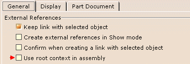
-
Select the Tools > Options > Equipment and Systems > Electrical Harness Discipline > Electrical Harness Installation > Harness Management tab.
Under Contextual Links, in the Keep link with selected object box, select In geometrical bundle.

Anyway, the system checks that the rules are not violated and if those options are not set properly, an error message is displayed:

Moreover, during the electrical connection between devices and/or bundle segments that are not inside the same workpackage, publications are automatically created on the geometrical bundle stored as workpackage, to ensure that constraints and connections are correctly stored.
Working with Geometrical Bundle in Explode Mode
![]()
Using the Explode mode, all the nodes of the
product structure are stored in ENOVIA V5.
This means that each component and its children are as many documents
visible in ENOVIA V5.
![]()
The geometrical bundles saved in explode mode cannot be used in Electrical Harness Flattening. It will not be possible to save the geometrical bundle extracted data. Use the workpackage mode in this context.
Within CATIA connected to ENOVIA V5 through to VPM Navigator, if the user selects a new component as a geometrical bundle, the system automatically knows that this geometrical bundle has to be stored in explode mode.
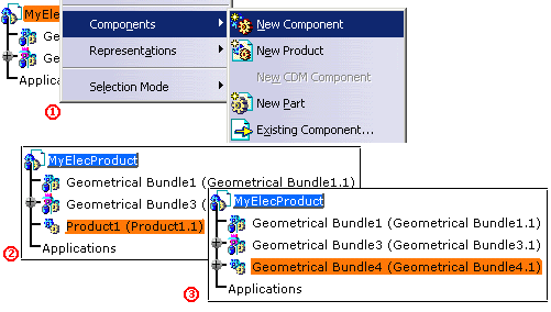
A single check is performed when using the Electrical tools to ensure that all the entities created or modified will be correctly stored:
The context for the external links must be set to the root
product node of the session.
Refer to Infrastructure User's Guide - Customizing Part
Infrastructure.
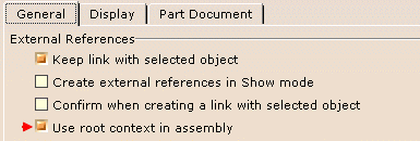
To make this possible, the following settings must be applied when working with CATIA connected to ENOVIA V5, to store the geometrical bundles in explode mode in ENOVIA V5:
-
Select the Tools > Options > Infrastructure > Part Infrastructure > General tab.
Under External References, select the Use root context in assembly check box.
Commands Not Supported in ENOVIA V5
In Electrical Library - Electrical Assembly workbench
Place Physical Device Add Link Remove Functional Link Define Mounting Equipment Define Equipment Define Shell Define Contact Define Filler Plug Define Back Shell Define Cavity Define Termination Define Connector Connection Point Define Bundle Connection Point Define Cavity Connection Point Define Back Shell Connection Point
In Electrical Wire Routing
New Wire Connection Move Connection Delete Connection Merge Connections Split Connection New Wire Select Signal