- create a CATDrawing document and save it in ENOVIA LCA
- retrieve the CATDrawing document in ENOVIA LCA
- view the documents which impact the CATDrawing in ENOVIA LCA
- open the CATDrawing document in CATIA V5
This task uses an assembly drawing (i.e. a drawing with views generated from a CATProduct document) as an example, but the same possibilities apply to part drawings as well.
Have a CATIA V5 and an ENOVIA LCA sessions running.
Creating a CATDrawing document and saving it in ENOVIA LCA
-
In ENOVIA LCA Product Class View, select a product and send it to CATIA V5.
For more information, refer to Sending an ENOVIA LCA Document to CATIA V5 in the ENOVIA-CATIA Interoperability User's Guide. -
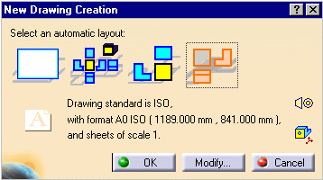
In CATIA V5, select Start > Mechanical Design > Drafting. The New Drawing Creation dialog box is displayed.
-
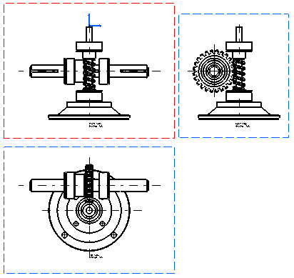
Select the views to be automatically created on your drawing, for example the Front, Top and Left icon.
-
Click OK. A progress bar appears while the views are being generated from the opened CATProduct.
The views are then displayed in the CATDrawing document.
-
Click the Save Data in ENOVIA LCA Server...
 icon to save
the drawing in ENOVIA LCA. The Save in ENOVIA LCA dialog box is
displayed.
For more information, refer to Saving an ENOVIA LCA Document from CATIA V5 in the ENOVIA-CATIA Interoperability User's Guide. -
Click OK to validate. The drawing is vaulted in ENOVIA, as well as the parts and products from which the views were generated. Note that the drawing is saved as a document in ENOVIA, it is not attached to a part at this moment.
Retrieving the CATDrawing document in ENOVIA LCA
-
In ENOVIA LCA, click the Search ENOVIA Tree
 icon in
the left-hand pane to perform a query in order to retrieve your
CATDrawing document.
 -
Select Content Management > Documents > Document. The Search dialog box is displayed.
-
In the Search dialog box, enter the name of your CATDrawing document and click OK. The search results are displayed in the bottom pane.
-
Right-click the CATDrawing document and select Copy from the contextual menu.
-
In ENOVIA LCA Product Editor, paste the document under the PRC.
Viewing the documents which impact the CATDrawing in ENOVIA LCA
-
In ENOVIA LCA Content Management, right-click the CATDrawing document (it can be either a part drawing or an assembly drawing) and select Send To > Impacted By. The Impacted By Tree View is displayed.
-
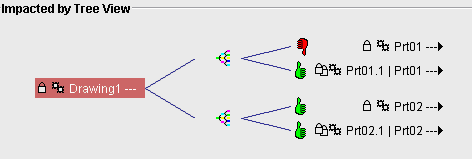
Double-click the CATDrawing document (here Drawing1) to expand the whole view of the product.
The drawing dependencies are displayed, letting you view the links between the CATDrawing document and the CATPart and/or CATProduct documents it references. This also lets you know whether the drawing is up-to-date or not.
In the examples below, Drawing1 identifies the drawing, and the
object identifies the drawing dependences.
Example 1
The thumb relates to the status of the branch: here the thumbs are up and green, which means that Prt01 and Property of Prt01 are synchronized with the Drawing1 object.
Since all elements are synchronized, the drawing is up-to-date.
Example 2
The red thumb down for Prt01 shows that it has been modified: it is not synchronized with the Drawing1 object.
Since not all elements are synchronized, the drawing is not up-to-date.
-
If the drawing is not up-to-date, you can update it using the following method:
-
Open the CATDrawing document in CATIA V5 (as described in Opening the CATDrawing document in CATIA V5 below).
-
Refresh it using the update
 icon.
icon. -
Save it using the Save Data in ENOVIA LCA Server...
 icon.
icon. -
Perform a local refresh in ENOVIA LCA using the Refresh
 icon.
icon.
If you now go back to the Impacted By Tree View in ENOVIA LCA, the drawing is indicated as being up-to-date.
-
Opening the CATDrawing document in CATIA V5
To be able to open only the CATDrawing document in CATIA V5, you need to send it from ENOVIA Content Management for example.
-
In ENOVIA LCA Product Editor, right-click the CATDrawing document and select Send To > Content Management.
-
In Content Management, right-click the CATDrawing document and select Send To > CATIA V5. The drawing is displayed in CATIA V5. In the case of an assembly drawing, the drawing links are broken.
-
To solve the links, perform as follows, depending on the save mode you chose when saving the assembly in ENOVIA LCA:
For an exploded assembly (i.e. saved as Document not kept & Product Structure Exposed): right-click the drawing in the specification tree and select Load PDM Context (you can also go back to ENOVIA LCA, right-click the associated CATProduct and CATPart documents in Content Management, and select Send To > CATIA V5). This loads the assembly drawing context (i.e. the CATProduct and CATPart documents used for the assembly drawing creation or for the last assembly drawing update) in the Product Structure editor in CATIA V5. Note that the part instances which were not referenced by the drawing when you last saved it are not loaded.
For a "black box" or "work package" assembly (i.e. saved as Document kept in vault & Publications Exposed): select Edit > Links... and choose the Pointed documents tab to visualize the links between the CATProduct and CATDrawing documents. From the list of pointed documents, select the CATProduct and/or CATPart documents you want to open, and click the Open button. This loads the selected documents in the Product Structure editor in CATIA V5.
The LoadPDM command will not load the technological package referenced by the drawing. The referenced technological packages can be listed via the Edit Links command, and have to be opened from LCA sessions.
A drawing references technological packages if it contains views created by selecting FT&A views stored in a technological package (View from 3D command).
Note that you need to load all the parts which make up a given product if you want them to be included in the drawing views at the next update.
The drawing links are now solved. The Drafting specification tree indicates whether the drawing is up-to-date or not, whether the drawing is a part drawing or an assembly drawing.
If the New Evolution and Replace Reference commands have been performed on a part or sub-assembly, the drawing links will not be solved by default on the new evolution of the part. However, you can force the solving of the links on this new evolution by going to Edit > Links > Replace and selecting the root product (PRC).
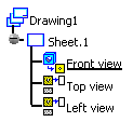
If a 3D element (product or part) has been modified before launching the drawing, the update mask appears in front of the drawing elements which need an update (all, in our example):
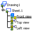
If no modification has been performed in 3D before launching the drawing, the various drawing elements in the specification tree are shown as being up-to-date:
Creating a CATDrawing from scenes saved in ENOVIA LCA (Technological Pacakages)
![]()
