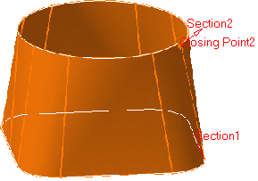
Creating Multi-Sections Surfaces

This task shows how to create a multi-section surface and includes the following functionalities:

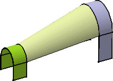
You can generate a multi-section surface by sweeping two or more planar section curves along a computed or user-defined spine. The surface can be made with respect to one or more guide curves.

Open the Loft1.CATPart document.

  1. Click Multi-sections Surface .

    The Multi-sections Surface Definition dialog box appears.
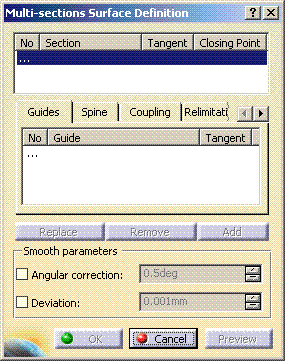
  2. Select two or more planar section curves.

    • The curves must be continuous in point.
    • You can select tangent surfaces for the start and end section curves. These tangent surfaces must not be parallel to the sections.
    • A closing point can be selected for a closed section curves.
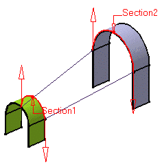
    • Sections can be 3D curves with following restrictions:
      • the intersection between one 3D profile and all guides must be coplanar (if three guides or more are defined)
      • in case of a user-defined spine, this spine must be normal to the plane implicitly obtained above.
  3. If needed, select one or more guide curves.
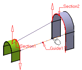
    It is possible to edit the multi-section surface reference elements by first selecting a curve in the dialog box list then choosing a button to either:
    • remove the selected curve

    • replace the selected curve by another curve

    • add another curve.

    More possibilities are available with the contextual menu and by right-clicking on the red text or on the object. For example, it is possible to remove and replace tangent surfaces and closing points.
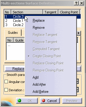
  4. Click OK to create the multi-section surface.

    The surface (identified as Multi-sections Surface.xxx) is added to the specification tree.

    Smoothing Parameters

    In the Smooth parameters section, you can check:
    • Angular correction to smooth the lofting motion along the reference guide curves. This may be necessary when small discontinuities are detected with regards to the spine tangency or the reference guide curves' normal. The smoothing is done for any discontinuity which angular deviation is smaller than 0.5 degree, and therefore helps generating better quality for the resulting multi-section surface.
    • Deviation to smooth the lofting motion by deviating from the guide curve(s).
     
    If you are using both Angular correction and Deviation options, it is not guaranteed that the spine plane be kept within the given tolerance area. The spine may first be approximated with the deviation tolerance, then each moving plane may rotate within the angular correction tolerance.

    Spine

    In the Spine tab page, check Computed spine to use an automatically computed spine or select a curve to impose that curve as the spine. 

    Relimitation

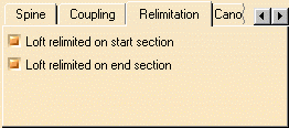
    The Relimitation tab lets you specify the multi-section surface relimitation type.
    You can choose to limit the multi-section surface only on the Start section, only on the End section, on both, or on none.
    • when one or both are checked: the multi-section surface is limited to corresponding section;
    • when one or both are unchecked: the multi-section surface is swept along the spine:
      • if the spine is a user spine, the multi-sections surface is limited by the spine extremities or by the first guide extremity met along the spine.
      • if the spine is an automatically computed spine, and no guide is selected: the multi-sections surface is limited by the start and end sections 
      • if the spine is an automatically computed spine, and one or two guides are selected: the multi-sections surface is limited by the guides extremities.
      • if the spine is an automatically computed spine, and more than two guides are selected: the spine stops at a point corresponding to the barycenter of the guide extremities. In any case, the tangent to the spine extremity is the mean tangent to the guide extremities.
    Multi-sections surface relimitation option checked on both Start and End sections
     
    Multi-sections surface relimitation option unchecked on End section only
     
    After the multi-sections surface is relimited, the following constraint needs to be fulfilled: the plane normal to the spine defined at the relimitation point must intersect the guide(s) and the point(s) resulting from this intersection must belong to the section.

    Canonical Elements

    In the Canonical Elements tab, check Canonical portion detection to automatically detect planar surfaces to be used as planes for features needing one in their definition.
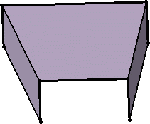
    Initial multi-sections surface with planar faces
     
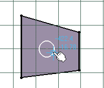
    Using a planar face as reference for a sketch
     

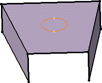
    Resulting sketch

 
  • You can impose tangency conditions onto sections and/or guides, by specifying a direction for the tangent vector (selecting a plane to take its normal, for example). This is useful for creating parts that are symmetrical with respect to a plane. Tangency conditions can be imposed on the two symmetrical halves.
    Similarly, you can impose a tangency onto each guide, by selection of a surface or a  plane (the direction is tangent to the plane's normal).  In this case, the sections must also be tangent to the surface.
  • You can create multi-section surfaces between closed section curves. These curves have point continuity at their closing point.
    This closing point is either a vertex or an extremum point automatically detected and highlighted by the system.
    By default, the closing points of each section are linked to each other.

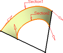
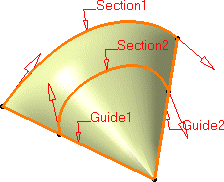
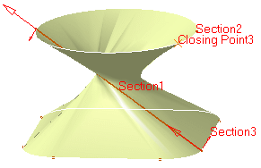
The red arrows in the figures below represent the closing points of the closed section curves. You can change the closing point by selecting any point on the curve. 

The surface is twisted:

A new closing point has been imposed to get a non-twisted surface: