- To see the material associated with a weld, see Seeing the Material Assigned to the Weld.
- This task must be performed using the Default Creation mode for weld, see Weld Creation Mode.
- To find more information about the weld creation options, see Weld Definition.
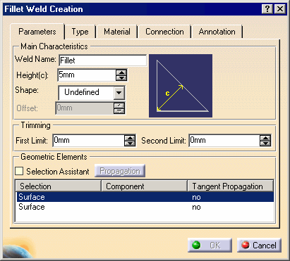
The Fillet Weld Creation dialog box is displayed.

-
Enter a meaningful name in the Weld Name field to identify your fillet weld: New Fillet
-
Select the Convex shape.
-
Enter a value to define the convex offset: 0.5 mm
-
Unselect Weld Symbol option in the Annotation tab.
-
To define how the fillet weld is trimmed, enter values to define both ends of the weld. For example, enter 5 mm in the first and second limit.
The application does not let you trim welds if the intersection between faces is closed.
-
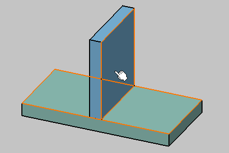
Select faces as shown on the green plate and blue plate with the following order: green plate, blue plate.
Two adjacent surfaces must be selected to define this type of weld.

-
Click the Connection tab to access additional options.
-
To identify the joint under which you will place the weld in the specification tree, enter a name in the Assembly Joint field (or keep the default name). For example, enter New Joint.
-
Create a new joint body in which you want to identify New Joint, and give a new name for the joint body: New Joint Body
-
Click the Material Assignment tab to define the material you wish to assign to the fillet weld as well as the part that will contain the resulting geometry.
-
Click OK to create the fillet weld.
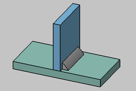
Taking a closer look at the fillet weld, you can notice that it was not created along the entire length of matching geometries as specified in the trimming options and that its surface is flat.
