This is a specification-related design rule and the associated table is located in the directory ...\intel_a\Startup\EquipmentAndSystems\XXXXX\Specification where XXXXX is the application name, such as Tubing.
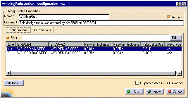
The first five columns in the table contain the input values: EndStyle1, EndStyle2, MinWallThickness, MaxWallThickness and FabricationSite. EndStyle1 is data from one part connector while EndStyle2 is data from the second part connector. Only one value is input for wall thickness - the columns MinWallThickness and MaxWallThickness constitute a range, inclusive of the values in the two columns. Wall thickness from each of the connectors must fall within this range. The value for the column FabricationSite is obtained from the Shop Fabrication design table.
If a user builds the Shop Fabrication table incorrectly, as a result of which the welding rule table gets both entries (shop and field), the first entry that it receives will be entered in the Fabrication Site field.
When all values match the input values, the table outputs the Weld Type. The value for weld type is used by the parts placement process to correctly select a weld.
You can enter any weld type keyword value relevant to your project in the WeldType column.
Calculation of the offset is hard coded in the application.
The default calculation is:
- Stub-on: Offset = square root of (OutsideRadRun² - InsideRadBranch²) + weld gap
- Stub-in: Offset = square root of InsideRadRun² - (OutsideRadBranch + weld gap)²
- Set-on: Offset = OutsideRadRun + weld gap
- Weld linear: Offset = weld gap
- Weld calculated: Offset = weld gap
If you want to change the default calculation you must implement a routine (CAA Interface) named CATICloAppWeldOffset.
You can add more weld end styles. To do this you must:
- Add entries to the branch rules table, making sure that the entry matches existing table conventions. Look at the table to find out what you need to add. Basically, you must identify the new parts that will use the new end style(s).
- Modify the CAA Interface (CATICloAppWeldOffset) to include the formula that must be used to calculate the weld offset for each new end style that you add. To add the formula you must change the code.
To sum up the process for calculating a Piping offset:
- The end styles needed by the welding rule are obtained from the branch rule table.
- The welding rule outputs the weld type.
- The weld type is used to select a weld part from the catalog.
- The weld gap is obtained from the weld part design table.
- The weld gap is used to calculate the offset for the selected end style, according to the formulae given above.
![]()