During the parts placement process the application will first examine the compatibility table to select the best connector match. The automatic parts rules takes over following this step and the application then:
- Looks at the automatic parts table to determine if a part should be placed between those two parts. It does so by examining the automatic parts table (see below). If an entry for the two parts in question exists in the table then it takes note of the part type. If there is no entry in the table then it decides that no part needs to be placed.
- It uses the part type defined in the table to retrieve parts from the catalog, and examines the compatibility table to determine the best match for the connectors (this process is explained in the compatibility rule). The part is then placed.
- The application will again examine the automatic parts table to determine if any part should be placed between the new part it just determined should be placed, and any of the existing parts. If another part is needed it will again check the compatibility table for best connector match. The application repeats this process until it determines that no more parts need to be placed.
- No more than 10 parts can be placed using this process. This is to prevent the application going into a loop because of incorrect rules table creation.
- You must check the Place Automatic Parts checkbox for the process to work. Go to Tools - Options - Equipment and Systems and click the Design Criteria tab. Check the Place Automatic Parts checkbox.
This is a general design rule and the associated table is located in the directory ...\intel_a\Startup\EquipmentAndSystems\XXXXX\DesignRules, where XXXXX is the application name, such as Tubing.
From Release 14 this rule can also be used as a specification-related design rule. The associated table should be located in the directory ...\intel_a\Startup\EquipmentAndSystems\XXXXX\Specification (or any directory specified by users) where XXXXX is the application name, such as Tubing.

The table has two sets of column headings, one set for each of the connectors to be used - PartType, Standard and EndStyle. A part will automatically be placed between two parts when: the values for these three attributes in the two connectors that are to be connected match one of the lines in this table.
For the PartType columns you can use the keywords "All" or "Not-".
Reading Line 1: If one part type is not a tubing nut, is from the standard SSTL and has the end style threaded male flared, and the other part type is a TubingStraightTube, is from the standard SSTL and has the end style flared tube, then place a tubing nut between the two parts.
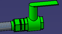
In the image below a flared tube was placed next to a valve, and the application automatically placed a union, a B nut and a sleeve between the tube and the valve.

![]()