This is a general design rule and the associated table is located in the directory ...\intel_a\Startup\EquipmentAndSystems\XXXXX\DesignRules, where XXXXX is the application name, such as Piping or Tubing.

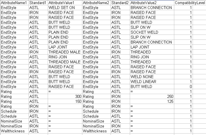
The table contains two sets of column headings (Attribute Name1 & 2 - Standard1 & 2 - Attribute Value1 & 2, and Compatibility Level - explained below). Attribute Name is the attribute, Standard is the name of the standard, while Attribute Value is the value for that attribute. When you place a part the application ensures compatibility by reading this table. It does so by determining if values for the connectors on the two parts match the values on one of the lines in the table. (Under the Standard1 column, if you enter an asterisk instead of a standard name, it acts as a wild card and the rule will work with any standard.)
It reads these values from the relevant connector only on the "place-on" part. For the part you select from the catalog ("place-to" part) it will examine all connectors to determine which is the best match. In the images below the user has placed a union with 3/4 and 1/2 inch ends against a 1/2 inch elbow. The application will select the connector that matches the elbow (1/2 inch).


COMPATIBILITY LEVEL: The compatibility level column is used when you want to override the compatibility design rule during part positioning. For normal design rule behavior you should enter the value 1 in this column. When you want to override normal behavior you should enter the value 0. In the table above, the compatibility level of the end style 'raised face' to the end style 'butt weld' is 0. Normally these two end styles are not compatible. and you will not be able to select a part with the value butt weld to place against a part with the value raised face. However, when you make an entry such as the one shown in the table the application will allow you to make such a selection from the catalog. At the same time the application will not use an entry with a compatibility level of 0 to position a part. To sum up: you will be able to select from the catalog, but the application will not consider raised face and butt weld as compatible while positioning parts.
You should also note that the automatic parts design rule will come into play when you place the end style 'butt weld' against 'raised face' - what it will do is add the necessary parts to make this configuration workable.
NOTE: If a part has an attribute and/or value that does NOT exist in the compatibility table, then the application will search in the catalog for parts that have that same exact value or attribute. For instance, the object against which you want to place a part has a nominal size of 12 inches, but the compatibility table does not have a) the attribute entry at all; or, b) has the attribute entry but not with a 12-inch size. In this case the application will search in the catalog for a part with the attribute nominal size and with a value of 12 inches. Parts that do not meet these criteria will not be considered.
Some symbols can also be used in the tables, as shown in the table above.
The equal (=) sign can only be used in the Attribute Value column. It means :
If it appears in both columns: these values have to be the same for both parts. It should not be used in one column only.
The asterisk can be used as a wild card, the value could be anything. The application will not try to find a match in the table.
![]()