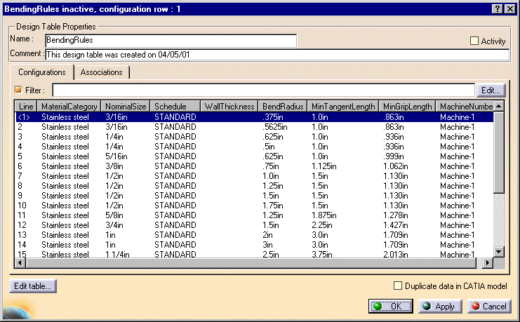
- The values for the attributes Bend Radius and Minimum Grip Length are used by two Knowledge Expert rules. The Knowledge Expert rules, which you can insert into your document, check that you do not exceed the maximum bend radius as defined in the table, and that the bendables you use have sufficient grip length. (See Using & Modifying Knowledgeware Rules.)
- The value for Minimum Tangent Length is used in the routing a run function to establish the minimum length of a segment.
- The value for the attribute Machine Number is not used by any function at the moment.
This is a standard-specific design rule and the associated table is located in the directory ...\intel_a\Startup\EquipmentAndSystems\XXXXX\Standards, where XXXXX is the application name, such as Tubing.

Column headings MaterialCategory, NominalSize, Schedule and WallThickness contain the input data. (At present WallThickness is optional.) If you are adding an entry then enter the relevant input data in these columns.
The columns BendRadius, MinTangentLength, MinGripLength and MachineNumber contain the output data. Enter the relevant output data in these fields.
Reading Line 1 above: for a 3/16" stainless steel tube from Schedule Standard (input data), the maximum bend radius should be .375 inches, the minimum tangent length should be 1 inch, the minimum grip length should be .863 inches and Machine 1 should be used to bend the tube (output data). If your design does not match any of the entries in the table then you will get an error message.
You must enter correct data for the attributes Material Category, Nominal Size and Schedule, or the rule will not work.
Data for WallThickness is optional, the rule will work with or without it. However, if you enter any value in the table then the part attribute must have the correct value also, or you may get an error message.
![]()