You can select More to display the Class Browser, and select from what is available in the catalog.
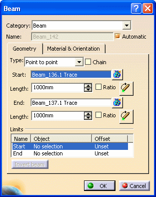
The name of the beam is assigned automatically, using the object naming rules. If you want to assign your own name to the beam, uncheck the Automatic box and enter a name.
If you select the Chain checkbox, the last end point selected becomes the start point of the next beam.

- Select the extremities of existing beams. (When your selection point is near the start, mid, or end point of a beam, these points become your selection point. However, you can select specific offset values.)
- Select a point in your 3-D session, or a point on the plane system grid. (Make sure the Selectable Points checkbox is selected on the Plane System Grid dialog box.) If you select the Chain checkbox, you can select as many points as necessary. The last end point selected becomes the start point of the next beam.
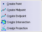
- Right-click and select from the list of GSD stacking commands.
You see the beams display in your 3-D session as you make your selections.

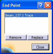
When selecting end points, you can click ![]() alongside the End field, and the End Point dialog
box displays.
alongside the End field, and the End Point dialog
box displays.
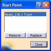
The Start Point and End Point dialog boxes list the points you selected.


You can use the dialog boxes to replace a point with another point.
- Select the start point you want to replace from the list, and click the Replace button.
- Select a point in the 3-D session. This start point displays in the Start Point dialog box list in place of the original start point. (The corresponding beam moves to the location of the point.)
The selected points are removed from the list, and the corresponding beams are deleted in the 3-D session, and in the specifications tree.
Click Close when you have made all the necessary changes.
NOTE: If the points you removed from the list were selected on the plane system grid, or were created using the list of GSD stacking commands, the points are removed from the 3-D session. If you used the Generative Shape Design workbench to create points, these points are not removed from the 3-D session.
NOTE: You must select the point on a beam to define a length or a ratio.
- Select an object in your 3-D session (reference plane, plate, stiffener, beam or pillar), and the beam is limited at that location.
- Right click to display a drop down list and select Select Reference Plane to display the Plane Systems dialog box. (You can select Delete Limit to delete a limit.)
NOTE: When you define a limit, the Invert Beam button becomes available. You can click it to invert a beam.
The Beam dialog box displays. Change the values as required.
Some fields are not available, and cannot be changed (such as Category).
