The procedure, described below, applies to both the Structure Detail Design and Structure Functional Design applications.
To learn how to edit and delete slots that you have placed in your 3-D session, see Editing and Deleting Slots.
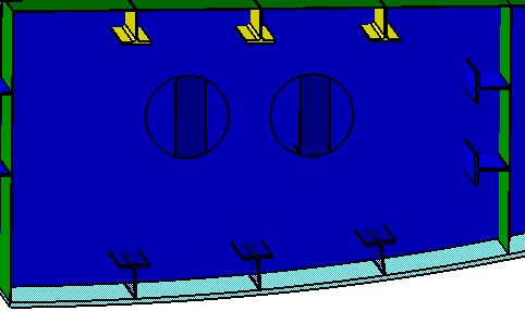
Select one or more plates in the 3-D session.
When you select a plate, it is highlighted in the 3-D session, and displays in the Penetrated Element field. In the example below, the plate is the transversal bulkhead.

When you select multiple plates, the selected number of plates display as elements in the Penetrated Element field.
NOTE: You can select plates or stiffeners as penetrated elements, but not a combination of the two.
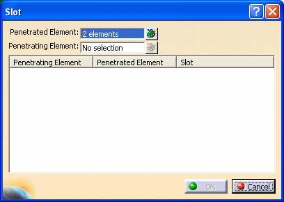
When you select a stiffener, it is highlighted in the 3-D session, and displays in the Penetrating Element field, and under the Penetrating Element column.
The previously selected penetrated elements display under the Penetrated Element column.
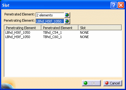
In the example above, when you select a penetrating element that penetrates more than one element, all the penetrated elements display in the Slot dialog box under the Penetrated Element column.
When you select multiple stiffeners, the stiffeners display as elements in the Penetrating Element field.
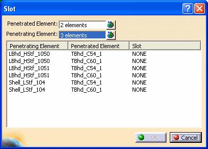
These stiffeners also are listed under the Penetrating Element column. When they intersect with a Penetrated Element, the penetrated elements are listed under the Penetrated Element column.
You can select a plate with multiple stiffeners as a penetrating element. All the stiffeners on the plate are then added to the list under the Penetrating Element column.
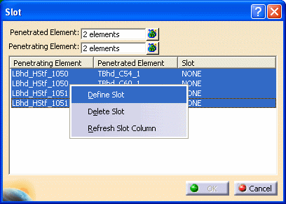
A second Slot dialog box displays.
An image of the selected slot displays in the dialog box.
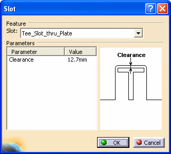
Change Parameter values as necessary. Click OK.
When the processing completes, the defined slots display under the Slot column for each of the penetrating elements selected.
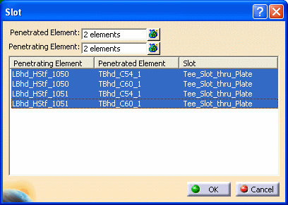
Click OK to close the dialog box.
Click the button beside the Penetrated
Element field
![]() .
The Elements List displays, listing the penetrated
elements you selected.
.
The Elements List displays, listing the penetrated
elements you selected.
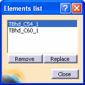
You can replace a penetrated element on the list with another penetrated element.
Select an element on the list that you want to replace, and click the Replace button. Select a penetrated element in the 3-D session, and this element displays on the Elements List in place of the original one.
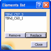
The replaced element also is listed under the Penetrated Element column in the Slot dialog box in place of the original one.
You can also remove penetrated elements from the list. Select the elements you want to remove, and click the Remove button. The selected elements are removed from the Elements List. Additionally, these elements are removed from the Penetrated Element list in the Slot dialog box.
Click Close when you have made all the necessary changes.
Click the button beside the Penetrating
Element field
![]() ,
and the Elements List displays, listing the
penetrating elements you selected.
,
and the Elements List displays, listing the
penetrating elements you selected.
You can replace a penetrating element on the list with another penetrating element.
Select the element you want to replace and click the Replace button. Select a penetrating element in the 3-D session, and this element displays on the Elements List in place of the original one.
The replaced element also is listed under the Penetrating Element column in the Slot dialog box in place of the original one.
You can also remove penetrating elements from the list. Select the elements you want to remove, and click the Remove button. The selected elements are removed from the Elements List. Additionally, these elements are removed from the Penetrating Element list in the Slot dialog box.
Click Close when you have made all the necessary changes.
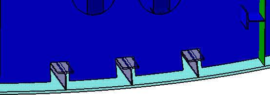
For Structure Detail Design:
The slots display as follows in your 3-D session.
For Structure Functional Design:
In the 3-D session, you see a blue square, which represents the slot.
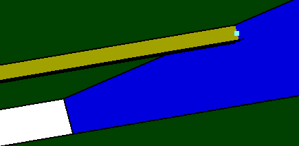
You also see ConnectionsSet in the specifications tree. ConnectionsSet is where information on all connections (such as slots) is stored and managed.
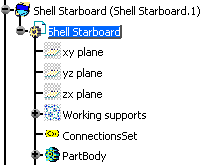
ConnectionsSet appears only once on the specifications tree, regardless of the number of slots or end cuts in your 3-D session.
If an object such as a stiffener is moved, the slot, represented by the blue square, does not move with the stiffener, and remains where placed in the 3-D session.
You must update ConnectionsSet.
To update ConnectionsSet information:
Right click on ConnectionsSet in the specifications tree. Select ConnectionsSet Object - Update from the drop down menus.
A message box indicates the information is updated.
After clicking OK, the slot (as a blue square) moves beside the stiffener where appropriate.
