Using Offset Planes and Advanced Offset Planes
|
|
This task shows you how to define a plane to use as a temporary reference for positioning other elements. The second part of the document explains the use of an advanced offset plane, which allows you to define origin, orientation and other parameters. | |
|
|
1. | Select the Offset Plane icon
|
| 2. | Define the reference plane by doing the following: | |
|
||
|
||
|
|
||
|
|
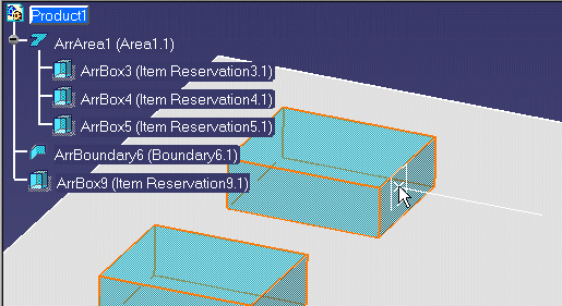
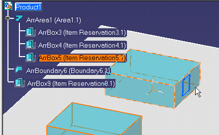
If you do not see the white rectangle, zoom out from the drawing. The white rectangle cannot be displayed if the element under your cursor is displayed too small. | |
|
||
|
||
|
|
||
|
||
| 3. |
Use the advanced offset plane feature to set your plane reference, origin and orientation settings as follows: |
|
|
||
|
||
| c. Click OK when done. The reference plane will be created. | ||
|
|
||