Inserting Nodes
|
|
This task explains how to insert one or more nodes in an existing run. | |
|
|
1. | Right click on the run and bring up the
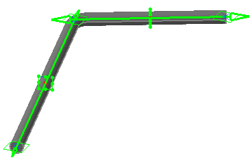
Definition dialog box. The run displays
all existing nodes.
|
| 2. | Right click on the segment in which you want to insert a
node and select Insert Nodes
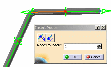
in the drop down menu. The segment you clicked turns red and the
Insert Nodes dialog box displays.
When the Insert Nodes dialog box opens the number of nodes is set to 1, and the node is located in the center of the segment. If there are parts on the run then it is on the open side of the first part. To change the number shown in the Nodes to Insert field, use the Up/Down arrows, or enter a number and press Enter. The node(s) will display in the run. You can click OK to place the node(s) at that location. Or you can use the process described below to place the nodes at locations defined by you. |
|
| 3. | Define center location
The node will be placed.
|
|
| 4. |
Define range to insert points
|
|
| 5. | To insert a node on a run
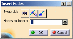
with a part on it: When the Insert Nodes dialog box
displays it will show the Swap Side symbol. This allows you
to shift the node you want to insert to the opposite side of the part.
In the image below you can see one node inserted.
Click the Swap Side button to place the node on the other side of the part. You can also do this more than one node.
You can use the "Define" buttons as explained above. |
|
| 6. | Click OK in the Insert
Nodes dialog box and again in the Definition
dialog box. A placed node looks like this:
|
|
![]()


