When managing drawings, SmarTeam lets you expose two types of links:
- CATIA Downstream Application
- CATIA Downstream Application-Reverse
As you create revisions, you can view and manage these associated objects using Associated Objects>CATIA Links. This command provides options corresponding to the different possible links.
In addition, SmarTeam color indicates each of the associated objects, so that you can clearly identify a document's links and reverse links.
-
Links are displayed in red (default color).
-
Reverse links are displayed in blue (default color).
The default color settings can be changed, as explained in Customizing color settings for associated objects.
Working with Links and Reverse Links
Each time you perform a life cycle operation on a document, you can view its associated objects, meaning its links and reverse links. You can then manage the revisions of these associated objects by checking the associated objects in or out of the vault or copying their files to your desktop.
When you check out (or check in) a Drawing, its associated document (the part/assembly) is automatically checked out together with the Drawing.
Viewing Associated Objects
You can view the links of a document and choose a lifecycle operation for each associated document. If you do not view the links of a drawing, the associated documents will automatically be checked out/in together with the drawing (if that is the default setting).
You can view the reverse links of a document and choose a lifecycle operation for them. If you do not view the reverse links of a document, then no lifecycle operation is performed on them.
For example: A Stump Preacher Explode A4 Drawing was created based on a Stump Preacher Guitar assembly . When you check out the Stump Preacher Explode A4 Drawing , its associated document, the Stump Preacher Guitar Assembly will be checked out with it (unless you display the linked document and choose a different lifecycle operation). When you check out the Stump Preacher Guitar Assembly , you may view and check out its reverse link, the Stump Preacher Explode A4 Drawing .
-
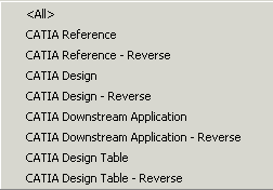
From any life cycle window (such as Check In or Check Out), right-click a drawing document and select Associated Objects > CATIA Links to display the list of view options which are as follows:


-
For example, select CATIA Downstream Application.
The product to which our drawing is linked is now displayed in red:
To manage associated objects:
When the associated objects are displayed in the tree browser, you can manage them in the same manner as any assembly and its children. You can:
-
copy the associated objects to the desktop, as shown above.
-
Check Out / Check In all the associated objects by choosing the Propagate Operation option.
-
handle each associated object individually. For each associated object, you can:
-
Check out or check in the document.
-
Copy its file to the desktop. The state of the document is not changed.
-
Choose No Operation for the document.
Life cycle operations are always performed on linked documents, even if you do not display them. This is not the case for reverse linked documents: You must choose to display reverse links in order to perform lifecycle operations on them.
-
Customizing Color Settings for Associated Objects
SmarTeam color indicates each of the associated objects, so that you can clearly view a document's links and reverse links.
|
To change these default settings:
-
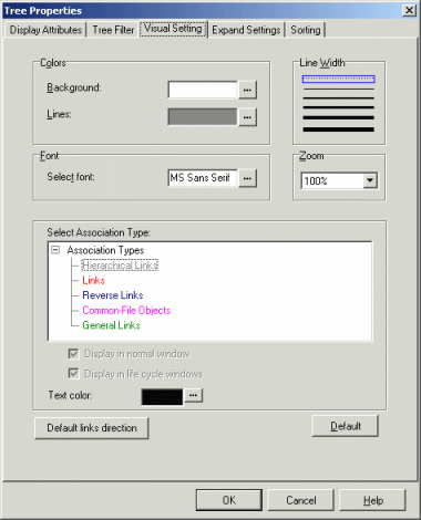
In any life cycle window, right-click to display a dropdown menu and choose Tree Properties.
-
Click the Visual Setting tab to display the following dialog box:

-
Click the button to the right of the color that you wish to change.
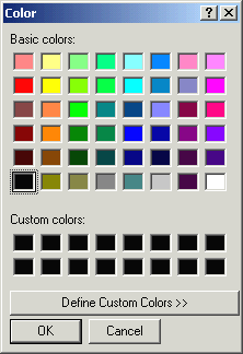
A color selection dialog box is displayed, as shown below:
-
Choose a new color.
-
Click OK to confirm and close the dialog box.
-
In the Tree Properties dialog box, click OK.