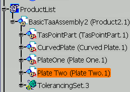
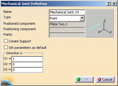
| Point |
|
Translation along x axis is locked. |
| Annular-Linear |
|
Translation along x axis is locked.
Translation along z axis is locked. |
| Edge Slider |
|
Translation along x axis is locked.
Translation along z axis is locked.
Rotation around z axis is locked. |
| Planar |
|
Translation along x axis is locked.
Translation along y axis is locked.
Translation along z axis is locked.
Rotation around y axis is locked.
Rotation around z axis is locked. |
| Spherical |
|
Translation along x axis is locked.
Translation along y axis is locked.
Translation along z axis is locked. |
| Spherical With Pin |
|
Translation along x axis is locked.
Translation along y axis is locked.
Translation along z axis is locked.
Rotation around x axis is locked. |
| Cylindrical |
|
Translation along y axis is locked.
Translation along z axis is locked.
Rotation around y axis is locked.
Rotation around z axis is locked. |
| Screw |
|
Translation along x axis and rotation
around x axis are linked.
Translation along y axis is locked.
Translation along z axis is locked.
Rotation around x axis is locked.
Rotation around y axis is locked.
Rotation around z axis is locked. |
| Revolute |
|
Translation along x axis is locked.
Translation along y axis is locked.
Translation along z axis is locked.
Rotation around y axis is locked.
Rotation around z axis is locked. |
| Prismatic |
|
Translation along y axis is locked.
Translation along z axis is locked.
Rotation around x axis is locked.
Rotation around y axis is locked.
Rotation around z axis is locked. |
| Rigid |
|
Translation along x axis is locked.
Translation along y axis is locked.
Translation along z axis is locked.
Rotation around x axis is locked.
Rotation around y axis is locked.
Rotation around z axis is locked. |