 |
This first task
shows you how to enter the Structure Design workbench and set up your
Version 5 session. In this task, you will:
|
 |
1. |
Select Mechanical Design ->
Structure Design from the Start menu. The Structure
Design workbench is displayed. |
| |
|
Associativity
To ensure associativity between the structure you are going to create
and the grid used as a construction aid, set the following options. |
| |
2. |
Select Tools -> Options
from the menu bar. |
|
3. |
Click Infrastructure ->
Part Infrastructure in the left-hand box of the Options dialog box,
then select the General tab. |
|
4. |
Check Keep link with selected
object and Synchronize all external references for update. |
| |
|
Visualizing Parameters and Relations
To display parameters and relations in the specification tree, set the
following options. |
| |
5. |
Still in the Part Infrastructure
category, select the Display tab. |
| |
|
Check Parameters to visualize
parameters in parts. |
| |
6. |
Click Infrastructure ->
Product Structure in the left-hand box of the Options dialog box,
then select the Tree Customization tab. |
| |
7. |
Set both Parameters and
Relations options to Yes to visualize parameters and relations in products. |
| |
8. |
Click General -> Parameters
and Measure in the left-hand box, then the Knowledge tab. |
| |
|
Check With value to display
parameters with values. |
| |
|
Creating a Grid
You will create a simple 3D grid defining the overall dimensions of your
foundation. |
| |
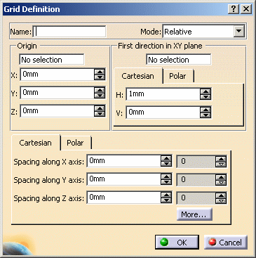
9. |
Click the Grid
 icon.
icon.The Grid Definition dialog box appears. |
| |
|
 |
| |
10. |
Enter a name for the grid you
want to create in the Name box: The grid will be identified by this name
in the specification tree. |
| |
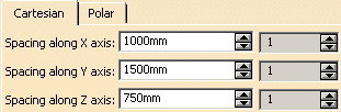
11. |
Specify Cartesian grid
coordinates to define the grid: Enter the distance between grid points in
Spacing boxes (1000 X 1500 X 750 mm respectively) as well as the number of
points along x, y and z axes, 1 in each case. |
| |
|
 |
| |
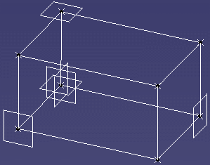
12. |
Click OK to create
the grid. The grid is created and is identified in the specification
tree. |
| |
|
 |
|
 |