|
|
This task shows how to create a special type of plate called an end plate. | ||||
|
|
1. | With your
product open, click the End-Plate
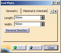
The End Plate dialog box appears. |
 |
||
| 2. | Click
the Material & Orientation tab and select material, grade and
thickness. See Material Management for more information. Material, grade and thickness are defined in the specifications catalog. |
||||
| 3. | Define the length and width of the plate using arrows to change the values or entering values directly in the fields. | ||||
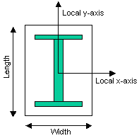 |
The length and width are defined with respect to the local axis system of the shape, for example, in the case of an I shape, the width is defined along the x-axis parallel to the flange and the length along the y-axis parallel to the web. | ||||
| 4. |
Select the end of the shape at which you want to place the end plate:
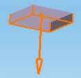
A preview appears. An arrow identifies the direction of extrusion. |
 |
|||
|
|||||
| 5. | Click the Custom
Attributes tab to change the values of attributes added by
the user. See Adding/Modifying Custom Attributes. These attributes can also be browsed and edited via the Properties dialog box. |
||||
| 6. | Click OK
when satisfied.
The end plate is created as defined and is added to the specification tree. |
||||
|
|
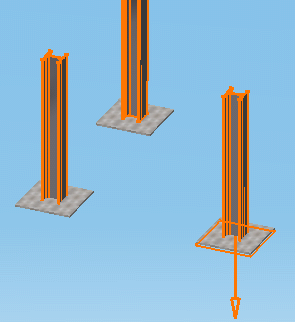
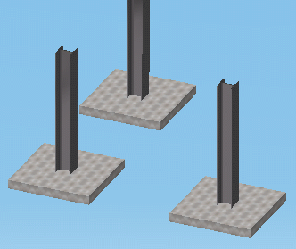
Creating Several Identical End Plates by Multiple SelectionSimply Cntrl-click to select more than one shape end and have several identical end plates created in one go. Changing the direction of extrusion or other plate characteristics applies to all end plates. |
||||
 |
 |
||||
|
|
|||||