This task explains how to define a corner relief locally on a set of supports.
Creating a circular or square Corner Relief
-
Click Corner Relief
 .
.
The Corner Relief Definition dialog box is displayed.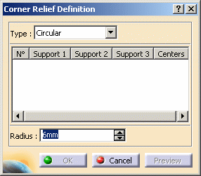
-
Select the type of corner relief you wish to create : circular or square (creating a local corner relief with a User Profile is explained in the second task of this topic).
-
Select the supports on which you want the corner relief to be created (here we chose Cylindrical Bend 1 and Cylindrical Bend 2).
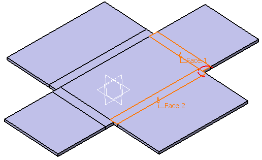

- You can create several corner relieves in the process, by selecting manually several bending faces.
-
You can select all the bending faces with the Select all command. This command is available with a right-click in the support field.


The Select All command only selects conical, cylindrical and planar bending faces.

By default the corner relief center is the barycenter of the supports but you can also define it, either by selecting an already exixting point or by creating it.
To create this point :- Select the corner relief on which you want to define the center with a left click
-
Right-click the line and select Create center.
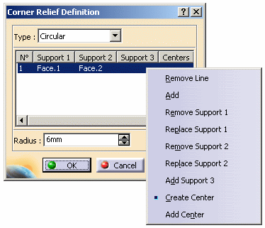
-
Create the point.
-
Click OK.
-
Enter the radius or length of the corner relief.
-
Click OK to create the corner relief.
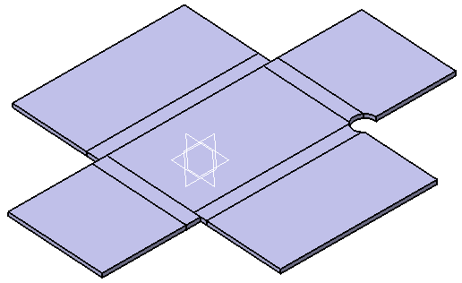
Creating a Local Corner Relief with a User Profile
The part needs to be unfolded prior to creating the corner relief.
-
Click Corner Relief
 .
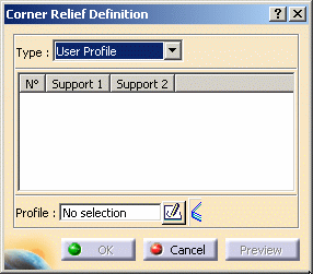
.The Corner Relief Definition dialog box is displayed. -
Select the User Profile type.
-
Select the supports on which you want the corner relief to be created (here we chose Cylindrical Bend 1 and Cylindrical Bend 2).
-
Select an already existing sketch or click Sketcher
 and select the xy plane.
 -
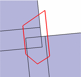
Click Profile
 and draw the sketch to define your corner relief.
-
Click Exit workbench
 .
. -
Click OK to create the Corner Relief.
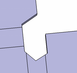

With a user profile type, you can only create one corner relief at a time.
![]()