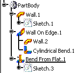
Open the NEWFlatBend1.CATPart document.
-
Click Bend From Flat
 .
.The Bend From Flat Definition dialog box opens. 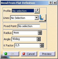
-
Select a profile (Sketch.3 here) containing one or several lines.
This sketch must contain lines only. 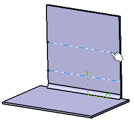
Selected lines appear in the Lines drop down list. 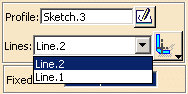

If necessary, you can create the profile in the Sketcher workbench using the Sketcher icon  .
.
The line(s) must not intersect an area where a 3D feature (such as a longitudinal chamfer, or a stamp created from punch and die) lies. -
You can choose the line extrapolation option:
 Axis
Axis  BTL (Bent
Tangent Line): line corresponding to the limits of the bend's fillet
BTL (Bent
Tangent Line): line corresponding to the limits of the bend's fillet IML (Inner
Mold Line): line created by intersecting the internal surfaces of the
bend (before filleting) and the wall
IML (Inner
Mold Line): line created by intersecting the internal surfaces of the
bend (before filleting) and the wall OML (Outer
Mold Line): line created by intersecting the bend support and a plane
perpendicular to the wall and normal to the OML.
OML (Outer
Mold Line): line created by intersecting the bend support and a plane
perpendicular to the wall and normal to the OML.The Radius and the KFactor values are the one defined when editing the sheetmetal parameters:
Right-click the Radius or the KFactor field and select Formula -> Deactivate from the contextual menu to change the value.You can set the Radius value to 0.
Once you chose the lines, the fixed point is automatically set on the face where the profile is lying.
It represents the part of the wall that will not move when the bend is created.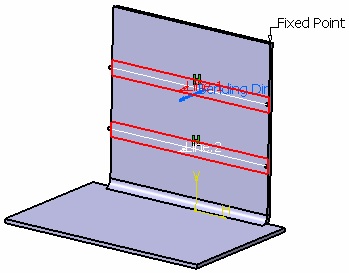
-
Select another fixed point as shown below.

Should you need to create the fixed point, right-click the Fixed Point field and select Create Point in the contextual menu. 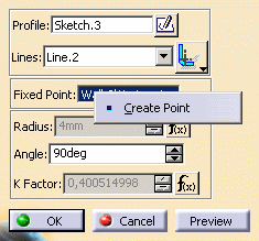
-
If needed, set the angle value for each line, using the Lines drop down list.
In our scenario, we selected 90 degrees for Line.1
You can invert the bending direction by clicking the blue arrow. -
Click OK to create the bend.

![]()