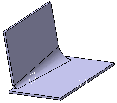
Conical bends are different from the standard bend in that they allow different radius values at each end of the bend.
Open the NEWBendExtremities01.CATPart document.
-
Click Conical Bend
 .
The Bend Definition dialog box appears.
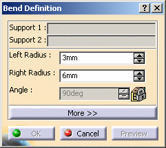
-
Select Support 1 and Support 2 in the specification tree or in the geometry area. The two supports must be connected by the edge of their internal faces.
The Bend Definition dialog box is updated, and arrows are displayed, indicating the walls orientation. When relevant (which is not the case in our example), you can click the arrows to invert the orientation. The left and right endpoints for the bend are identified using text. 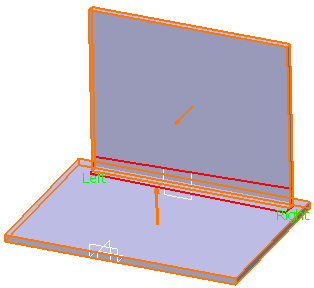
-
Enter the radius values for each end of the conical bend. For example, enter 5mm as the left radius and 20mm as the right radius.

-
By default, Right Radius amounts to twice Left Radius.
-
Note that the radius is computed based on the left and right endpoints for the bend. This radius, once computed, will be larger than the specified value.
-
When the size of each support differs, the bend may exceed the top of the cone. In such a case, computing the radius value is impossible.
The Angle field is locked. If you then click the Preview button, it is updated, indicating the angle value between the two walls between which the bend is computed. 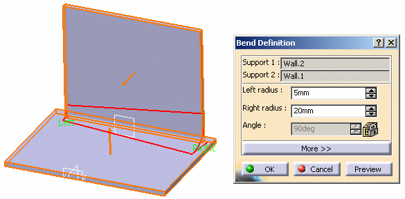
-
-
Click More... to display additional options.
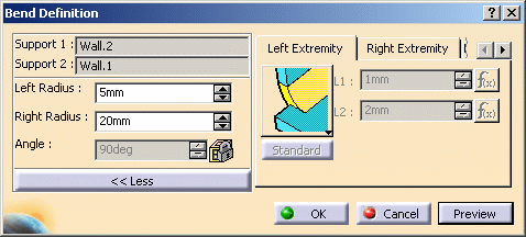
You can define:
-
the left and right extremity settings (see also extremities definition settings)
-
and the bend allowance settings.
-
-
Click OK. The conical bend is created.

For more information on closed bends, refer to Creating Bends from Walls.
![]()