This task explains how to create
a wall by extrusion.
You can extrude sketches composed of lines, circles, projection of lines,
and projection of circles.
A model is available in the Extrude1.CATPart from the samples directory.
-
Click the Extrusion icon
 .
. -
Select a sketch.
The Extrusion Definition dialog box is displayed.
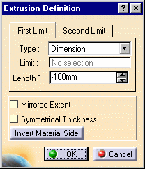
- Dimension : the requested input data are a sketch and a dimension,
- Up to plane or Up to surface: a plane or a surface are input as limit to the extrusion. These functions are used to create walls that are not rectangular.
-
Edit the Length1 and Length2 to set both extremities, for option Dimension.
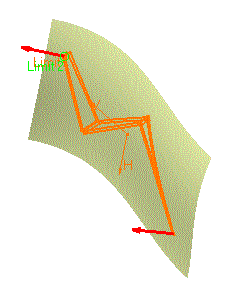
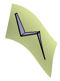
-
Define the options as needed:
- Check the option Mirrored extent to extent the material on both sides of the sketch. In that case, only Length1 can be edited.
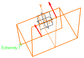
This option is only available if the type is set to Dimension.
- Check Symmetrical thickness to create thickness inside and outside the sketch.
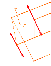
- Push Invert Material Side to invert the direction of the creation of the material.
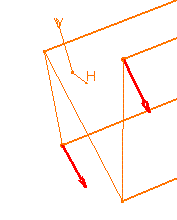
-
Click OK.
The walls corresponding to the selected sketch are created according to the specified options, and added to the specification tree.
- When the extrusion is the first Sheet Metal feature of the Part, the reference wall is the first wall created based on the first segment of the sketch.
- For option Up to Surface, while the wall end that is limited by the surface has the shape of the surface, its thickness does not fit the surface. It is a "rectangular" polygon defined by the first edge that comes into contact with the surface.

- Such an extrusion can also be performed on a sketch made of lines and
arcs of circle, provided there are no tangency discontinuities between
the different elements.
However, in this case:- the Up to plane or Up to surface capabilities are not available,
- you cannot isolate such an extrusion,
- if the element of the extruded sketch connected to the part is an arc of circle, the extrusion will not display in the unfolded view. To avoid this, prefer to create a User Defined Flange or remove the arc of circle of the extruded sketch and create a bend to connect the extrusion to the part.
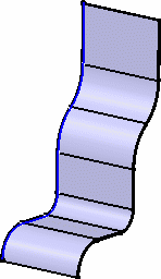
- Extrusion walls can be edited and/or isolated.
![]()