![]()
![]()
You must be in the Sheet Metal Workbench, with a .CATPart
document open, and you must have defined the
sheet metal parameters.
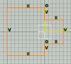
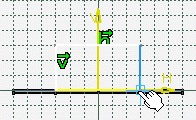
Set the sketcher grid to H = 100mm and V = 100mm,
using the Tools -> Options, Mechanical Design -> Sketcher,
Sketcher tab.
![]()
-
Click the Sketcher icon
 then select the xy plane.
-
Select the Profile icon
 .
.
-
Sketch the profile as shown below:
-
Click the Exit workbench icon
 to return to the 3D world.
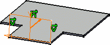
![]()
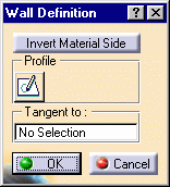
By default, the Material Side is set to the top.
-
Click OK.
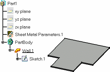
The Wall.1 feature is added in the specification tree.
![]()
The first wall of the Sheet Metal Part is known as the Reference wall.
- Click the sketcher icon
 from the
Wall Definition dialog box, if you wish to directly edit the selected
sketch. When exiting the sketcher, you then go back to the wall creation
step, without having to reactivate the Wall icon.
from the
Wall Definition dialog box, if you wish to directly edit the selected
sketch. When exiting the sketcher, you then go back to the wall creation
step, without having to reactivate the Wall icon.
This is also very useful if you have selected an edge from a wall and clicked the Wall icon
.
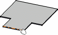
In this case, the sketcher is automatically activated and the plane defined as being the selected edge's plane.
You can then directly draw a sketch, then exit the sketcher and return to the wall creation step.
- You can directly create a wall with a hole, by selecting a sketch with an inner profile (the profiles must not intersect):
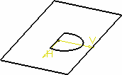
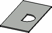
Note however, that the emptied area is part of the wall and is not a separate cutout that can be edited.
![]()