Open the FlatBend1.CATPart document from the samples directory.
-
Select the reference wall then the Bend From Flat icon
 .
.
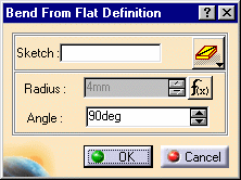
The Bend From Flat Definition dialog box opens.
-
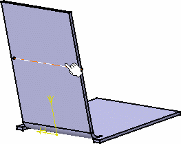
Select a sketch (Sketch.3 here).
This sketch must necessarily be a line.
-
You can choose the line extrapolation option:
-
 the line is extrapolated up to the wall edge (Bend From Flat Until)
 -
 the line is not extrapolated, and the bend is limited to the line's length
(Bend From Flat Length)
The Radius value is the one defined when editing the sheetmetal parameters:
Right-click the Radius field and select Formula -> Deactivate from the contextual menu to change the value.
-
Set the angle value between the generated wall and the reference wall.
-
Click OK to create the bend.
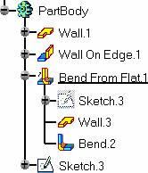
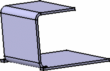
- When creating such a bend on a reference wall (first wall), an arrow indicates which part is to be folded. Click this arrow to invert the side that will be bent.
- Such bends cannot be created, if the section to be folded already intersects the part.
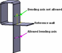
- Bends from line should be performed on end walls, or prior to creating further walls on the bent one.
- Perform the bend before creating the stamping features, as stamps are not retained when the part is folded with the bend.
![]()