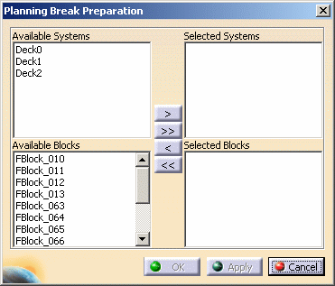
This dialog box allows you to select the system loaded in the session, and functional volumes for which you want to generate planning breaks.

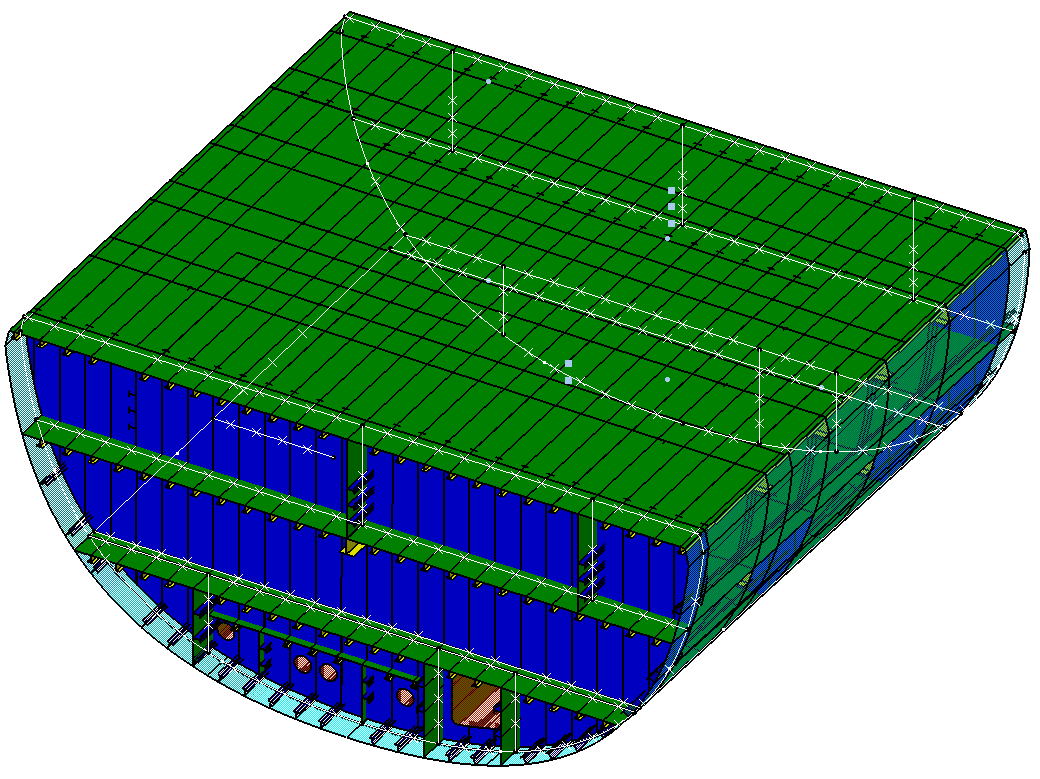
- A planning break is placed on all sides of the block, except where it adjoins the hull.
- A planning break does not impact a pillar, meaning a pillar will not be 'cut' by a planning break. However a beam is impacted.
- If a pillar runs vertically through two or more functional volumes, it is included in the functional volume in which its top is located.
- If the limits of two functional volumes are shared, one planning break will be created between them.
- If the same object (e.g. deck) is on the boundary of two functional volumes, then the application uses special rules to decide in which functional volume the deck should belong. See Confusion Rules.
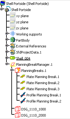
- one Planning Break Manager,
- one PlanningBreak folder,
- several Plate or Profile Planning Breaks,
- several Functional Volume proxy (e.g. DSG_1110_1000).
NOTE: A Functional Volume proxy is defined in each SFD system, even if no object is assigned to it.
