 |
This task explains creation of a coaming on an opening using a free edge
stiffener. |
 |
A
"free edge'' is the end of a plate that is not limited by another object.
This could be a deck that does not run the entire length of the ship, in
which case the edge that is not limited by the hull is considered free
edge. Or it could be openings in the deck, the edges of the openings being
free edges. Web girders also have free edges. Stiffeners are often placed
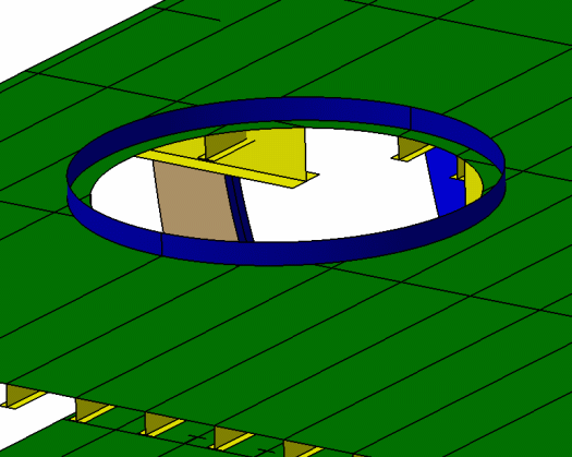
on these free edges to strengthen them. The image below shows a free edge
stiffener placed on an opening in a deck.
 |

|
1. |
With your
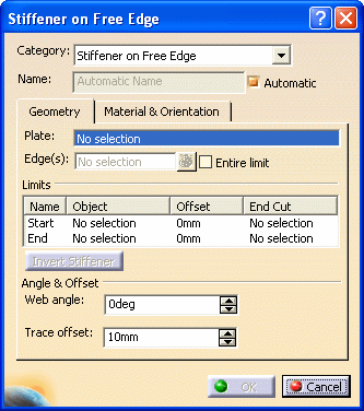
document open click the Stiffener on Free Edge button
 to open the
Stiffener on Free Edge dialog box. to open the
Stiffener on Free Edge dialog box.

If you select the plate on which you want to place
the stiffener before you open the dialog box it will be pre-selected. You
can change the selection by clicking in the Plate field and
selecting a plate in the specifications tree, or in the viewer. As soon as
a plate is selected the free edges in it highlight and can be selected.
When you move your mouse pointer over an edge it changes color. The image
below shows the free edge of an opening, and the free edges of the deck,
highlighted in blue.

|
| |
2. |
CATEGORY:
Select a category by clicking the down arrow in the Category
field, in this case stiffener on free edge. |
| |
3. |
NAME: The
application can assign a name to the object you are creating using the
object naming
function if you check the Automatic checkbox. If you want to
assign your own name then uncheck the box and enter a name. |
| |
4. |
EDGE: This
field displays the free edges that have been selected. You can select more
than one edge, and view them in this field. The
Entire Limit checkbox allows you to place stiffeners along all
joined free edges, if they were defined with a sketch.
In the deck opening shown above, the free edge has
been defined using a sketch, and consists of a circle. If you select the
Entire Limit checkbox the stiffener will be placed on the entire
edge. If you uncheck the option, the stiffener will be placed only on the
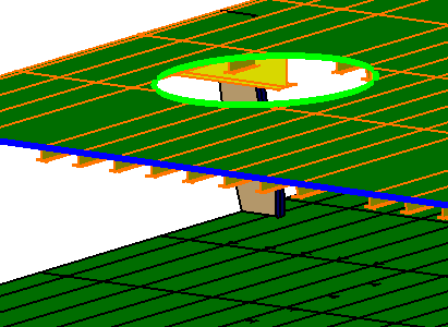
element you select. In the image below, the Entire Limit
checkbox is selected, and the mouse pointer has been moved over the
opening. The stiffener will place on the green portion only.

You should note the following behavior:
When the Entire Limit checkbox is not
selected, stiffeners placed on all contiguous edges will be combined into
one. Initially they will display separately in the specifications tree, but
will be combined once you click the OK
button. This will happen if they were defined using the same process. If in
the same document you have free edges that were defined using a sketch, and
others that were defined using a non-sketch method, then:
- All stiffeners placed on contiguous free edges
defined by a sketch will be combined into one.
- All stiffeners placed on contiguous free edges
defined by a non-sketch method (e.g. planes) will be combined into one.
|
| |
5. |
Click the
button next to the Edge field to display the Elements List. You
can use the list to delete or replace stiffeners that you have added. To
replace, select the free edge, click the Replace button, then
select the new free edge. |
| |
6. |
LIMIT: By
default, stiffeners are placed from end to end of the free edge you
selected. If you need to resize a stiffener, you have to define the
limits.
Under Limits,
in the
Name field, select Start and select a starting
limit. You can select a plane, plate, another stiffener or a surface. The
stiffener is limited as soon as you make your selection.
Use the same method to define the
End. Under Offset, you can define the offset
value of each stiffener on free edge limit. |
| |
7. |
WEB ANGLE: By
default the web of a stiffener is placed perpendicular to the plate. If you
want to place it at an angle then enter the preferred angle in this field,
or use the Up/Down arrows. This option is available for both face plate and
free edge stiffener types. |
| |
8. |
TRACE OFFSET:
This option is only available for a stiffener with free edge, and is the
distance from the edge that the stiffener is offset. The default is always
10 mm. You can adjust according to your needs. In the first image above you
can see that the coaming has been offset from the edge. |


