Defining Orientation

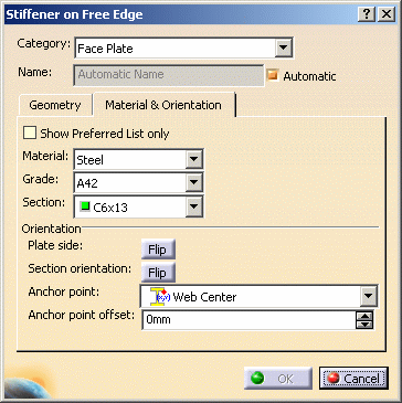
This task explains how you can define the orientation properties of a free edge stiffener. See Defining Material for Profiles for an explanation of material properties.


1. With your document open click the Material & Orientation tab in the Stiffener on Free Edge dialog box.

The Anchor Point Offset field is only active when you select the Face Plate category.

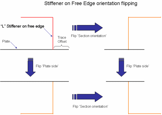
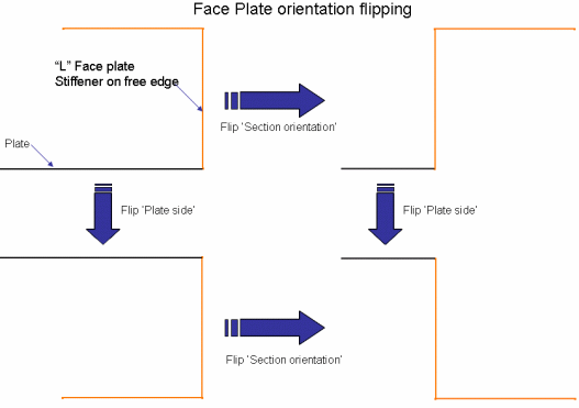
  2. You can perform several actions In the Orientation section. Click the Plate Side Flip button to toggle the stiffener from one side of the plate to the other.

Click the Section Orientation Flip button to toggle the section about the web. The images below show both operations.
  3. Select an anchor point for the stiffener.

NOTE: The anchor points that display in the Anchor Point field are defined in the file ShipStructureMoldedConventions.xml.  See Defining Molded Conventions for more information.
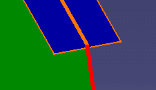
  4. Anchor point offset: This allows you to modify the location of the anchor point of a face plate stiffener. As an example, a stiffener with a center-right anchor point, and 0 mm offset, is positioned equally to either side of the plate, as shown below.

Changing the offset value moves the stiffener more to one side or the other. The images below show a stiffener that is not offset (left) and one that has been offset.
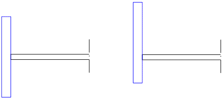
NOTE: The changed offset will not be visible to you in the document. However, the information will be stored in the document and the stiffener positioned as you indicated when thickness is added to the parts in downstream processes.

  5. Click OK when you have made your selections.