Defining Molded Conventions

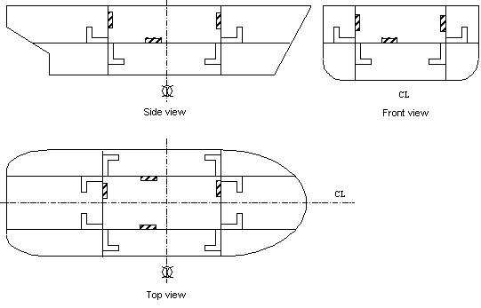
Molded conventions are a set of rules that give default orientations when placing structural elements, thereby ensuring structural continuity. These conventions are defined in the file ShipStructureMoldedConventions.xml, which is referenced in the Project Resource Management (PRM) file.

The default location for this file is ../OS/Startup/EquipmentAndSystems/Structure

This file describes conventions for plates and stiffeners of both Structure Functional Design and Ship Structure Detail Design products. Plates and stiffeners are oriented according to their location in the hull and with respect to the midship or centerline. Midship and centerline definitions are specified in another XML file describing project parameters (ProjectParameters.xml).
Important: Conventions are specified for each object class of plates and stiffeners defined in the feature dictionary.

NOTE: There is a DTD (Document Type Definition) file associated with this XML file. The DTD file enforces certain rules to which the XML file must adhere. If you make any change in the XML file, you must make sure they follow strictly the rules laid out in the DTD file. (You must not make any change in the DTD file.) The application will not function if you do not follow these rules. Also, the DTD file, by default, is located in the same directory as the XML file. If you change the location of ReferencePlanesSystem.xml then you must do the following:

  • Enter the new location of ReferencePlanesSystem.xml in the PRM file.
  • In ReferencePlanesSystem.xml, provide the full path to the DTD file. This should be added in the DOCTYPE entry at the top of ReferencePlanesSystem.xml.
 

Placing Structural Elements

The system administrator can modify the following information:

For Plates

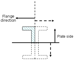
  • ThicknessOrient: the side of the support on which plate thickness is oriented


For Stiffeners

  • PlateSideOrient: the side of the plate on which the stiffener is placed
  • SectionOrient: orientation of the stiffener flange
 
  • AnchorPoint: the point at which the stiffener section is anchored along its trace.
 

For Stiffeners on Free Edge

  • AnchorPoint: the point at which the stiffener section is anchored along its trace.

Symbols Used

The following is a list of orientations that can be used to specify molded conventions. This list is defined in ShipStructureMoldedConventions.dtd. The default location for this file is ../OS/Startup/EquipmentAndSystems/Structure
 

Symbols used for orientations (ThicknessOrient of plates, PlateSideOrient and SectionOrient of stiffeners):


HP: Horizontal Plus. Nls name : Top
HM: Horizontal Minus. Nls name : Bottom


LP: Longitudinal Plus. Nls name:
Portside if FrontOrientation = Xp in ProjectParameters.xml (Front of the ship correspond to X+ )
Starboard if FrontOrientation = Xm in ProjectParameters.xml (Front of the ship correspond to X- )
LM: Longitudinal Minus. Nls name:
Starboard if FrontOrientation = Xp in ProjectParameters.xml                        

Portside if FrontOrientation = Xm in ProjectParameters.xml


LI: Longitudinal Inboard. Nls name: Inboard
LO: Longitudinal Outboard. Nls name: Outboard

NR: Normal of support plane.
IV: Inverted normal of support plane.

TP: Transversal Plus. Nls name:
Fore if FrontOrientation = Xp in ProjectParameters.xml
Aft if FrontOrientation = Xm in ProjectParameters.xml
TM: Transversal Minus. Nls name:
Aft if FrontOrientation = Xp in ProjectParameters.xml
Fore if FrontOrientation = Xm in ProjectParameters.xml

TI: Transversal Inboard. Nls name: Inboard
TO: Transversal Outboard. Nls name: Outboard

OtherI: Other Inboard. Nls name:
Inboard for shell plates or shell stiffeners
Normal for plates using Other category (this orientation corresponds to the normal vector of the support used to create the plate)
OtherO: Other Outboard. Nls name:
Outboard for shell plates or shell stiffeners
Invert for plates using Other category (opposite of the normal vector)

Anchor Point Definition

An entry from the ShipStructureMoldedConventions.xml file is reproduced below. It determines the anchor points that are available when placing the given object - in this case a stiffener.

  • StiffenerClass Name - the name of the object.
  • DefaultAnchorPoint - the default anchor point you get when placing the object.
  • AnchorPoint Name - the anchor points that are available in the Anchor Point field of the dialog box. Each anchor point should be entered on a separate line, as shown below.

<StiffenerClass Name="DeckStiffener" PlateSideOrient="HM" SectionOrient="TI"
                           DefaultAnchorPoint="catStrWebSideLeft">
  <AnchorPoint Name="catStrWebSideLeft"/>
  <AnchorPoint Name="catStrWebCenter"/>
  <AnchorPoint Name="catStrWebSideRight"/>
</StiffenerClass>

Following are the values that can be used to define DefaultAnchorPoint and AnchorPoint Name:

catStrBottomLeft
catStrBottomCenter
catStrBottomRight
catStrCenterLeft
catStrCenterCenter
catStrCenterRight
catStrTopLeft
catStrTopCenter
catStrTopRight
catStrGravity
catStrWebSideLeft
catStrWebSideRight
catStrWebCenter
catStrWebCenterLeft
catStrWebCenterRight


2D View Orientation

To set the orientation of the object when it opens in the Sketcher change the settings in the following line of the ShipStructureMoldedConventions.xml file as explained below.


<SuperPlateClass Name="DeckPanel" ThicknessOrient="HP" Orient2D_U="XP" Orient2D_V="YP">

  • Orient2D_U - orientation in the U direction.
  • Orient2D_V - orientation in the V direction.

The valid values you can enter are as follows:

XP: X Plus
XM: X Minus
YP: Y Plus
YM: Y Minus
ZP: Z Plus
ZM: Z Minus
NA: Not Applicable (orientation attribute ignored. Example, orientation does not
apply to shell plates.)

end of task