 |
-
Click Draft Reflect line
 from the Volume drafts sub-toolbar.
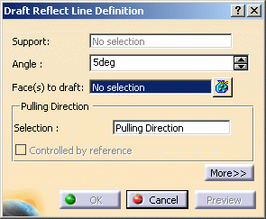
| The Draft Reflect Line Definition dialog box is displayed and an
arrow appears, indicating the default pulling direction. The default
direction is normal to the face. |
| You can click on the arrow to reverse the direction. |
 |
-
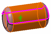
Select the cylinder.
| The application detects one reflect line and displays it in pink.
This line is used to support the drafted faces. |
|
The Support field is filled with the
volume owning the selected face. |
 |
-
Enter an angle value in the Angle field. For example,
enter 11. The reflect line is moved accordingly.
-
Click Preview to get an idea of what the draft
will look like.
-
Click More>> to access further options.
-
Check Define parting element and select plane
zx as the parting element.
-
Click OK to confirm the operation.
|
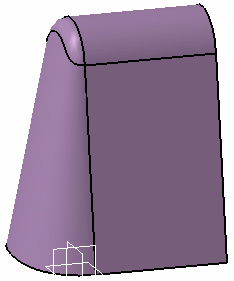
The element (identified as Draft.xxx) is added to the
specification tree. |
 |
 |
For further information about
limiting elements, refer to Creating Basic Drafts in Part Design
documentation. |
|
![]()