This task shows how to create a curve by defining its equation as a law.
You must have
access to the Knowledge Advisor product.
Make sure the Relations and Parameters options are
selected in the Tools > Options > Infrastructure > Part
Infrastructure > Display tab.
Open a new .CATPart document.
-
In the Generative Shape Design workbench, define a working support using Work on Support
 .
.The Work On Support dialog box appears. 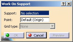
-
Select the yz plane, for example, and click OK in the updated Work On Support dialog box without modifying any other parameter.
The Working Support.1 is created, and the system automatically moves into this plane. You now want to create a horizontal line as the abscissa axis. -
Click Line
 .
.The Line dialog box is displayed. -
Right-click in the Point 1 field, and choose the Create Point contextual menu.
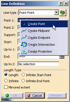
The Point Definition dialog box is displayed, the Point type and Plane fields being automatically filled. 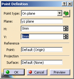
-
Create a point at H:0mm and V:0mm, and click OK.
-
Repeat the operation, right-click the Point 2 field from the Line Definition dialog box to create another point at H:100mm and V:0mm, then click OK in the Point Definition dialog box.
-
Click OK in the Line Definition dialog box to create the line.
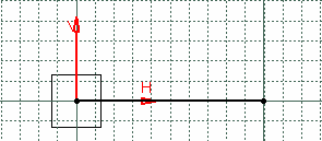

You may want to hide the grid by checking the Hide grid option from the Work On Support dialog box.
-
From the Knowledge toolbar, click Law
 .
.The Law Editor dialog box is displayed in which you name the law to be created, give it a description and a storage location. 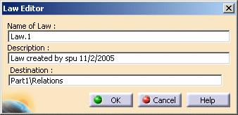
-
Click OK.
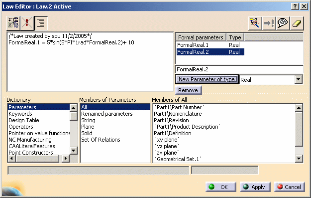
The Law Editor dialog box is updated. The right-hand part allows you to create the parameters to be used in the law. The left-hand part is the law edition box. -
Create two real type parameters FormalReal.1 and FormalReal.2, then enter the law below into the edition window: FormalReal.1 = 5*sin(5*PI*1rad*FormalReal.2)+ 10
-
Click OK to create the law.
-
In the Generative Shape Design workbench, click Parallel Curve
 .
.The Parallel Curve Definition dialog box is displayed. -
Select the line created in Step 7 as the reference Curve.
-
Click Law... and select Law.1 from the specification tree.
-
Click OK.
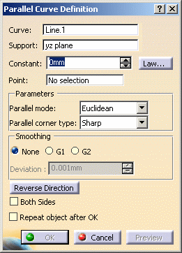
A curve parallel to the selected one is created, taking the law into account, i.e. it is defined by the equation entered as a law using the Knowledge Advisor. 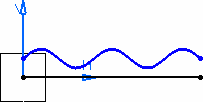
![]()