 |
This task explains creation of a web girder or bracket.
The process is essentially the same as that of creating a transverse
bulkhead, with the important differences that a web girder or bracket is
limited by objects, and a sketch (which is a free edge). |
 |
The process of creating a web girder or bracket is the same, with a
difference that is explained below. This task explains the steps needed to
created a web girder. The same steps can be used to create a bracket. |

|
1. |
Create an SFD
system under the tertiary system (see Organizing
Your Document), rename it if necessary. Select the CATPart that is
created under the system in the specifications tree and go
Start - Equipment & Systems
- Structure Discipline -
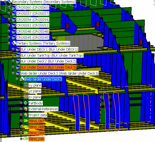
Structure Detail Object Design. The image below shows finished web
girders (highlighted at the lower part of the image), along with the
specifications tree structure.
 |
|
|
2. |
Click the
Plate button  to
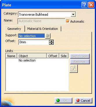
display the Plate dialog box. The entries are explained below: to
display the Plate dialog box. The entries are explained below:
 |
| |
3. |
CATEGORY:
Click on the down arrow to display the entries - they will include the
last 10 entries that you selected. If Transverse Bulkhead is not displayed
then select More to display the Class Browser and make your
selection from that list.
NOTE FOR BRACKETS:
If you are creating a bracket then select Other in the
Category field. This allows the bracket to be at any angle, and the
molded conventions are not applied. Bulkheads are limited to an incline of
not more than 45 degrees. |
| |
4. |
NAME: The
application can assign a name to the object you are creating using the
object naming
function if you check the Automatic checkbox. If you want
to assign your own name then uncheck the box and enter a name. |
| |
5. |
SUPPORT: Select a cross as
the location for the bulkhead - once you select a cross the bulkhead
is placed (in preview mode). Your selection displays in the Support
field. |
| |
6. |
LIMITS: This function trims
the excess plate.
To do this, select under Limits, and select the objects you want to use to limit the
web girder. (In this example, shell and upper and
lower deck.)
The plate is trimmed, and the Object
field displays the objects you selected.
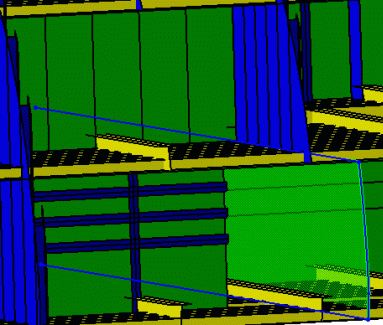
The image below shows the trimmed web girder. The fourth side is not yet trimmed.

Under Offset, you can define the offset value of each
plate limit. A positive value adds material. A negative value removes
material.
Additionally, limit tags display in your 3-D session to assist with
plate limit management.
The Remove button allows you to delete a
limit.
The Switch Side button lets you toggle
between limited sides. You can also switch sides by selecting the same
limit again. |
| |
7. |
Click the
Sketcher button  .
The Sketcher application opens with the support object selected as the
sketch plane. However, it may not be visible because of the hull
structure, in which case click the Cut Part by Sketch Plane
button .
The Sketcher application opens with the support object selected as the
sketch plane. However, it may not be visible because of the hull
structure, in which case click the Cut Part by Sketch Plane
button  to make it
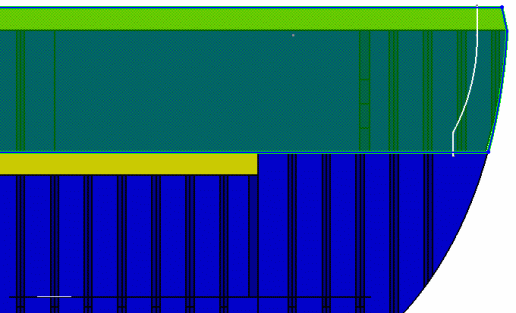
visible. Use one of the Sketcher tools to draw a 'limit' to the web
girder. The image below shows part of the hull and the web girder, with a
line drawn at the location where it will be limited. to make it
visible. Use one of the Sketcher tools to draw a 'limit' to the web
girder. The image below shows part of the hull and the web girder, with a
line drawn at the location where it will be limited.
 |
| |
8. |
Exit the
Sketcher. The web girder will be limited at the line you drew. |
| |
9. |
To place more
than one web girder, select the Support field again and select
your supports - in this case the planes. The web girders will be placed
with the same limits used in placing the first one. |
| |
10. |
Click OK
when you have finished. |


