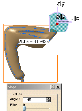
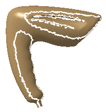
This type of analysis identifies lines on the analyzed element where the
deviation
from the slope direction at any points corresponds to a specified value.
The Z axis gives the view direction.
If the deviation angle=0, the lines are the zones of the analyzed element
where the normal is orthogonal
to the view direction (apparent contour).
If the deviation angle is different from 0, the lines are the zones where
the normal is orthogonal
to the view direction increased by the angle.
-
Click Segmentation by Slope Criterion
 and select the mesh.
 -
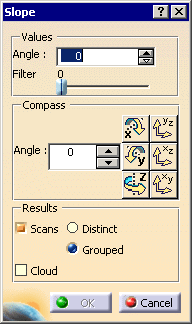
The dialog box is displayed.
The compass is put on the mesh. By default, the angle is set to 0.
-
Use the Values/Angle fields to set the angle of the deviation with the view direction.
-
Use the Compass/Angle field and the Compass icon to set the view direction.
Or manipulate the compass as you wish.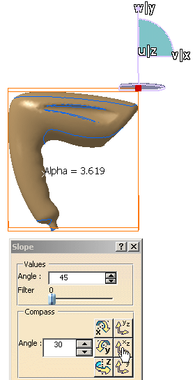
-
Use the Filter spinner to reduce the number of points of the lines.
-
If you sweep the cursor on the mesh, the deviation angle is displayed.
-
Click OK to create the result. You can choose to create:
-
Scans, either distinct or grouped:
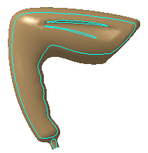
Scans.x elements are created in the specification tree.
-
or Clouds, that is sub-meshs:
Sub Mesh.x elements are created in the specification tree.
These meshs can then be processed with the Basic Surface Recognition action, for example.
The input mesh is sent to the NoShow.
-
![]()