and how to create the corresponding editable surfaces:
-
Click Basic Surface Recognition
 .
.
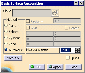
The Basic Surface Recognition dialog box is displayed.

-
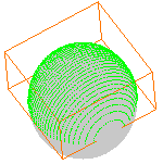
Select the type of surface to detect or click Automatic and Apply to visualize the shape.
-
For each type of surface, you can choose to let the application compute the surface
or you can set some data:- For a plane: the normal to the plane and its passing point,
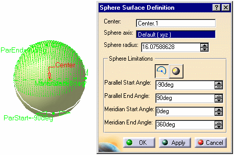
- For a sphere: the center and the radius,
- For a cylinder: the radius, the axis and the center,
- For a cone: none,
- For the automatic check box: the maximum plane error.
Those data are also displayed in the dialog box when the surfaces are
computed by the application. -
You can activate the corresponding fields by selecting their names and
edit the values as necessary before creating the surfaces.
- If you choose a shape type to recognize, you can edit its geometric
properties
(Axis, Center, Radius) by activating the corresponding select boxes and entering new values. - If the shape recognized is a plane, you can edit it graphically, using
the extension
(arrows) and rotation (circle) manipulators.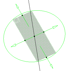
- If you click Automatic, you cannot modify the geometric
properties of the shape directly.
Once the shape has been recognized, select the corresponding shape type to make
the corresponding properties editable. - Click Apply to take those modifications into account.
-
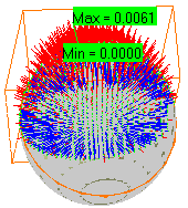
Select the Spikes check box to display the deviation between the canonic surface and the original part.
-
Click More>> to display the statistics on the action.
-
Click OK to create the shape.
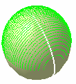
-
Double-click the shape to edit it, if required:
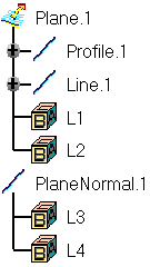
The normal to that plane named PlaneNormal.x and its components
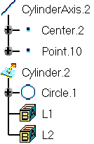
The axis of that cylinder named CylinderAxis.x and its components.
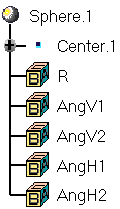
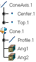
The axis of that cone named ConeAxis.x and its components.
![]()