-
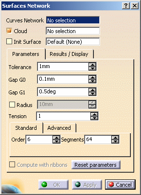
Click Surfaces Network
 .
The dialog box is displayed.
.
The dialog box is displayed.
-
Select the curves network you have created (mandatory),
as well as the mesh as the Cloud. -
Select Init Surface check box if you want to use one.
The init surface helps the computation by giving the shape of the result surface.
You can either select it yourself or let the application compute it in the direction of the largest curve.
If you select an init surface, its name is displayed in the field Init Surface.
- It is not necessary to use a support Cloud or a Init Surface, but they may improve the output.
- The init surface must be larger than the domain to process.
-
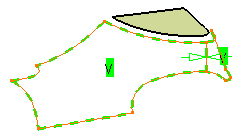
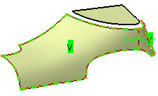
The curves network is displayed, with a green V marker on each wire, meaning the wire will be filled.
-
You can fill all the wires automatically (this is the proposed default) or you can fill the wires one by one.
-
If you do not want to fill a wire:
- either click its marker, it will turn into a red X marker. The
wire will not be filled.
(Click marker again to reselect the wire, if necessary), - or place the cursor on a marker and use the contextual menu:
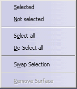
- Selected and Not selected apply to a single wire,
- Select all and De-Select all apply to the whole network,
- Swap Selection reverses the selection.
- Remove
Surface allows you to suppress a surface you are not
happy with
or that you prefer to fill later.
- either click its marker, it will turn into a red X marker. The
wire will not be filled.
-
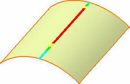
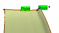
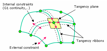
Constraints are set on edges shared by two wires.

represents a point continuity 
represents a tangency continuity
To change the type of a constraint:
either click its marker. This will act as a toggle,
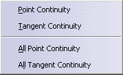
or place the cursor on a marker and use the contextual menu:
- Point Continuity and Tangent Continuity apply to a single constraint,
- All Point Continuity and All Tangent Continuity apply to the whole network.
-
You can set the Tolerance, which is the mean maximum deviation between the surface created
and the cloud of points or mesh, i.e. the deviation may be higher at some places. This field is editable. -
You can set Gap: G0, which is the distance between the surface and the boundary curves.
Since there is more noise on points than on curves, the Tolerance may be higher than the GO Gap.
The default value is 1.
-
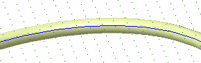
You can set Gap: G1, which is the tangency tolerance between two contiguous surfaces (in blue below).
The default value is 0.5.
-
You can set the Radius:
- when the cloud of points is noisy, it is difficult to have the
surface going through all the points
and the curves (risk of undulations).
The points inside a circular pipe centered on the curve are deleted, and you may want to set
the radius of that pipe.
- When you select this check box, a blue sphere is displayed on
the extremity of the first curve,
representing this radius
(if you have selected at least one curve and a cloud of points or a mesh).
If two curves are not distant enough, all the points between them may be deleted,
making the computation of the surface impossible.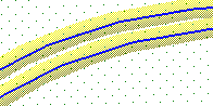
- when the cloud of points is noisy, it is difficult to have the
surface going through all the points
-
You can set the Tension:
Possible values are between 0 and 4.
Use a higher value to have a tenser surface.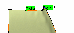
-
You can set Standard: Order, Segments:
These parameters apply globally to the surface computed. They are maximum values.
The actual values are computed automatically by the action.Surfaces Network creates a NURBS surface, controlled by the tolerance (i.e. Tolerance),
the number of segments and their order.
Whenever possible, this surface consists of one single segment,
otherwise, it is made of several segments.
This surface may then be trimmed by the curves.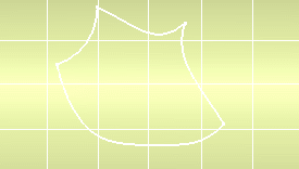
You can increase the order of the segments, thus reducing their number, or vice-versa. - If the number of segments is x, this means that the surface
computed will consist of
a maximum of x segments, or less.
The default number of segments is 64, the maximum number is 2048.
- If the order of segments is y, this means that each segment will
have a maximum number
of y control points in each direction, or less.
The segment order may vary from 3 to 15.
- If the number of segments is x, this means that the surface
computed will consist of
-
You can set Advanced: Order and Segments in U and V. You may want to impose an order
and a number of segments in both U and V direction. To do so, go to the Advanced tab.
You can edit the fields to:
- type the number of segments in each direction,
- type the order of segments in each direction.
Click Apply to restart the computation.
- Increasing the order of the segments may result in an oscillating surface,
even if this is not visible.- Typeing a global number of Segments in the Standard tab is different
from typeing the square roots of the global value for the Segments in U and in V
in the Advanced tab:
if you type a global value of 64 segments in the Standard tab, this is a maximum value,
that may be distributed in 14 segments in U and 4 in V,
whereas if you type 8 segments in U and 8 segments in V,
the maximum number of segments in U will be 8, the surfaces computed will thus be different.
-
You can select the Compute with ribbons check box
This check box is only available if a mesh is selected and is used when a tangent continuity is
required between the wires.The wires curves are projected on the mesh and a tangency ribbon is computed on the mesh
around the curve projection, and then taken into account for the computation of the filling surface.
-
Click Reset parameters to reset the parameters, if necessary.
-
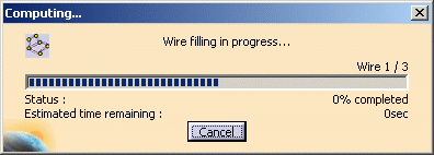
Click Apply button. The filling surface is computed. A progress bar is displayed.
-
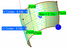
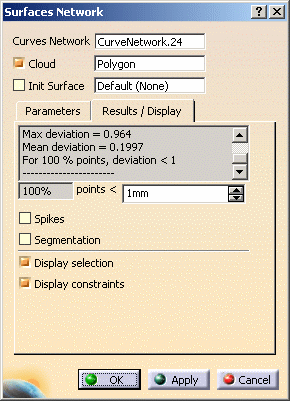
Go to the Results/Display tab.
Information on the points for the parameters taken into account by the computation are available
in the box at the top of the tab (no dynamic display):-
the maximum deviation found between the points of the cloud and the surface,
-
the mean deviation found between the points of the cloud and the surface.
This deviation should be as small as possible. -
the percentage of points of the cloud that are below the mean deviation.
-
-
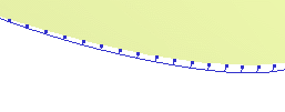
Select the Spikes check box to display the deviations.
-
Select the Segmentation check box to display
- the segmentation on the surfaces computed,
- the number of segments and order in U,
- the number of segments and order in V.
-
Use the Deviation field
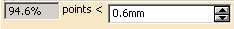 to type the value
above which the deviation spikes will be displayed.
When you first enter the action, the Deviation value is the same as the Tolerance.
Once a surface has been computed, the Deviation value is the computed one.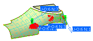
-
By default, the check boxes Display selection and Display constraints are selected.
You can unselect them according to your needs. -
Once you are satisfied, click OK to create the result:
the surfaces are assembled (Tolerance = 0.1 mm)- If the assembly does not respect the tolerance an error message is issued.
- If the assembly failed, an error message is issued and the surfaces are created separately.
A Surface.xx element is created in the specification tree.
![]()