 |
This task shows you
how to access and edit component properties. You can redefine and even
create new ones at any time. |
 |
Open the
ManagingComponents01.CATProduct document. |
 |
-
Right-click CRIC_AXIS (CRIC_AXIS.1) in
the specification tree and select Properties from the
contextual menu.
You can select the component in the specification tree or in the
geometry. This command is also available from the Edit
menu.
The Properties dialog box is displayed. Four tabs are available:
- Product
- Graphic
- Mechanical
- Drafting
-
Click the Product tab in the Properties
dialog box.
|
 |
In a CATProduct,
the Instance Name must be unique at one Assembly level. If you
enter the same Instance Name as the existing one in the document, at the
same level, there will be a red light in the Instance Name field:
 , with the following message :
"The identifier xxx.n is already used". , with the following message :
"The identifier xxx.n is already used".Neither special characters
"!" and ":" nor an empty name " " and blank
character at end of the string should be used in the:
- Instance Name
- Part Number
- Publication.
The Component frame displays:
- Instance name, the name of the selected component
- Description, the description of the selected component.
The Product frame displays:
- Part Number, the name of the product
- Revision
- Definition
- Nomenclature
- Source
- Description.
The combo box displays the following options:
- unknown: for an unknown product
- made: for a product made by the user
- bought: for a product bought by the user.
The InstanceName attribute is only valuated on the first instance. |
|
|
-
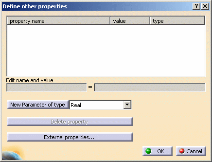
Click the Define other properties button.
The dialog box that appears lets you add the properties of your
choice.
|
| |
Here is the list of the new parameters you can add:
|
| |
-
Select the parameter you need next to New
Parameter of type. For example, select String,
and then click New Parameter of type. This parameter is
displayed in the property name frame.
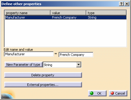
-
Rename the parameter as Manufacturer in
the Edit and value field.
|
 |
Be careful when choosing a name for a parameter, as some
correspond to attributes shortcuts and/or attribute names and should not
be used. For more information, refer to the Using the Search Language
chapter in the CATIA Infrastructure User's Guide. |
| |
-
Enter French Company in the value field.
The dialog box now looks like this:
-
Clicking Delete property
deletes the selected parameter.
-
Clicking External properties... accesses additional
properties defined in a .txt or .xls file. The application can reuse
these files provided they have a tabulated format.
-
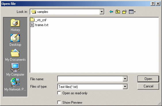
To do this, select the desired file, trame.txt for example, in the
Open File dialog box that appears:
-
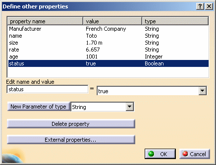
Click Open and the information
contained in trame.xls are stored in the Define other properties
dialog box:
-
Click OK in the Define other
properties dialog box to validate the creation of the property.
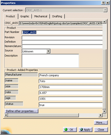
A new section Product: Added Properties appears in the
Properties dialog box. This section displays all the properties
you have created, even those described in the .txt or .xls files.
Once created, you can access these
properties via the
Bill of Material too.
-
Click the Graphic tab in the
Properties dialog box.
|
 |
This tab lets you
display the Graphic properties of the component. To know
how to apply graphic properties, refer to
CATIA- Infrastructure User's Guide. |
|
-
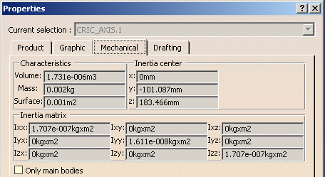
Click the Mechanical tab to display the
mechanical properties of the selected component:
- Characteristics: Volume, Mass and Surface. The fields are not
editable. Note that the mass is 0kg because no material has been
applied. For more about materials, please refer to CATIA-Real
Time Rendering User's Guide.
- Inertia center. The corresponding fields are not editable.
- Inertia Matrix. The corresponding fields are not editable.
|
| |
-
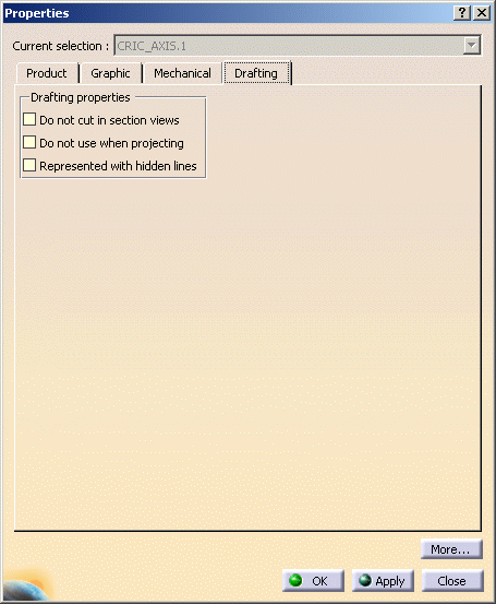
Click the Drafting tab in the Properties
dialog box.
-
Specify the properties that should be used for this
component when generating views:
-
Do not cut in section views: the component will not
be cut when projected in section views.
-
Do not use when projecting: the component will not be
projected in views.
-
Represented with hidden lines: the component will be
represented with hidden lines.
|
| |
Note that these properties may be overloaded by editing view
properties directly in the Drafting workbench.
|
|
-
Click OK to validate the operation.
|
 |
