Open the Pocket1.CATPart document and make Body.1 as the current feature.
Creating a Multi-Pocket
-
Click Multi-Pocket
 .
. -
Select Sketch.4 that contains the profiles to be extruded. Note that all profiles must be closed and must not intersect. In case a profile would be open, the application would not take it into account.
The Multi-Pocket Definition dialog box appears and the profiles are highlighted in green. For each of them, you can drag associated manipulators to define the extrusion value.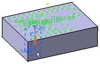
The red arrow normal to the sketch indicates the proposed extrusion direction. To reverse it, you just need to click it.
The Multi-Pocket Definition dialog box displays the number of domains to be removed. In our example, the application has detected six domains, as indicated in the Domains section.

-
Select Extrusion domain.1 from the dialog box.
Extrusion domain.1 now appears in blue in the geometry area. -
Specify the length by entering a value. For example, enter 10mm.
-
You need to repeat the operation for each extrusion domain by entering the value of your choice. For example, select Extrusion domain.2 and Extrusion domain.6 and enter 30mm and 40mm respectively.
-
Note that you can multi-select extrusion domains from the list before defining a common length: multi-select Extrusion domain.3, Extrusion domain.4, and Extrusion domain.5, then enter 50 as the common length value.
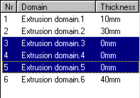
-
Click More>> to expand the dialog box.
In the Second Limit field, you can specify a length value for the direction opposite to the direction previously defined.
Note that the Thickness section displays the sum of two lengths defined for a given extrusion domain.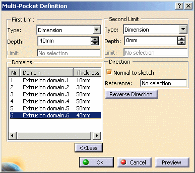
Unchecking the Normal to sketch option lets you specify a new extrusion direction. Just select the geometry of your choice to use it as a reference.
-
Click OK to create the multi-pocket.
The multi-pocket (identified as Multi-Pocket.xxx) is added to the specification tree.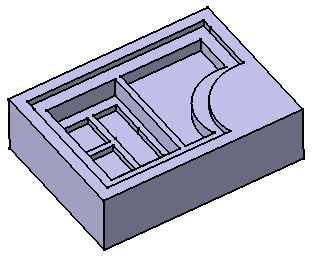
Editing the Multi-Pocket
The rest of the scenario shows you what happens when :
Adding an Extrusion Domain
Example 1: the new profile is sketched outside existing extrusion domains
-
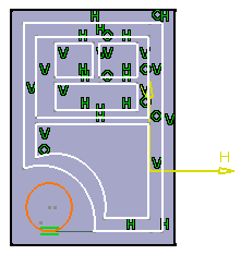
Double-click Sketch.4 to edit it: for example, sketch a closed profile outside Extrusion domain.1.
-
Quit the Sketcher. A warning message informs you that the application has detected that the initial geometry has been modified. Click Close to close the window.
-
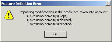
Double-click MultiPocket.1. The Feature Definition Error window displays, providing the details of the modification.
-
Click OK to close the window.
The Multi-Pocket Definition dialog box reappears.
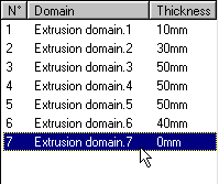
The new extrusion domain Extrusion domain.7 is indicated. -
Select it and define the value of your choice.
-
Click OK to confirm.
Multi-pocket.1 is now composed of seven pockets.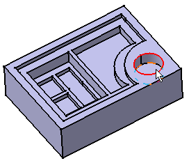
-
Double-click Sketch.4 to edit it: for example, add a closed profile inside Extrusion domain.2.
-
Quit the Sketcher. A warning message informs you that the application has detected that the initial geometry has been modified. Close the window.
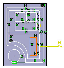
-
Double-click MultiPocket.1. The Feature Definition Error window displays, providing the details of the modification:
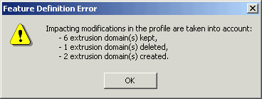
When sketching a profile inside an existing extrusion domain, the application deletes that existing domain and replaces it with a new one. This is why the message window displays:
- 1 extrusion domain deleted (Extrusion domain.2)
- 2 extrusion domains created (Extrusion domain.8 and Extrusion domain.9, that replaces Extrusion domain.2)
-
Click OK to close the window.
The Multi-Pocket Definition dialog box reappears. Extrusion domain.2 is no more displayed. On the contrary, two new extrusion domains Extrusion domain.8m Extrusion domain.9 are indicated with 0mm as their default thickness.
-
Select Extrusion domain.8 and define 40mm as the length value.
-
Select Extrusion domain.9, that is the rectangle, and define 30mm as the length value.
-
Click OK to confirm.
Multi-pocket.1 is now composed of eight pockets.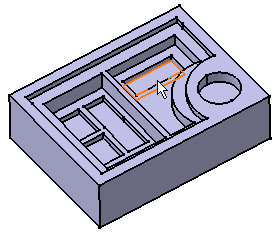
Deleting an Extrusion Domain
-
Double-click Sketch.4 and delete Extrusion Domain.5.
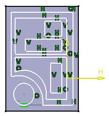
-
Quit the Sketcher.
The application has detected that the initial geometry has been modified: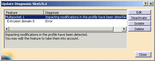
-
To tackle the problem, you can:
- edit, deactivate or even delete MultiPocket1.
- or you can edit or delete Extrusion domain.5
Make sure that MultiPocket.1 is selected and click the Edit button. The Feature Definition Error window displays, providing the details of the modification.

-
Click OK to close the window.
The Multi-Pocket Definition dialog box reappears. Only seven extrusion domains are indicated in the Domains category.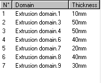
-
Click OK to confirm.
The new multi-pocket feature is composed of seven pockets.