- validate a Reaming operation for an H7 hole
- find a tool using a tolerance range
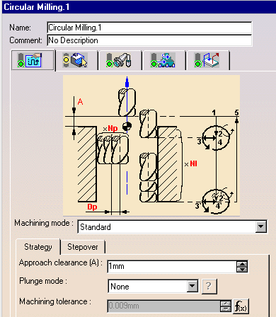
- parameterize Circular milling parameters according to minimum and maximum values.
This capability makes use of the Functional Tolerancing & Annotations
TPSPackage Knowlegdeware package. You can load this package under Tools
> Options > General > Parameters and Measures. In the Knowledge tab page,
select the Load extended language libraries checkbox and choose
TPSPackage as the package to load.
See Functional Tolerancing & Annotations User's Guide for more information.
 File
     -> Open
then select the
Tolerances.CATPart document.
The part is displayed in the Part Design workbench.
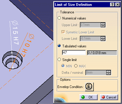
The Limit of Size Definition dialog box appears.
For the selected Diameter 10 H7 tolerance, the tabulated values are set to H7 and 0 / 0.018mm as minimum / maximum values. Click OK to quit the dialog box.
These values can be accessed in Knowledgeware expressions using the following functions:
- SemanticDimTabValue for the Hole quality (H7 in the example above)
- ToleranceMin (or SemanticDimLowerLimit) for the minimum value (0mm in the example above)
- ToleranceMax (or SemanticDimUpperLimit) for the maximum value (0.018mm in the example above).
These functions can be used in Machining Processes (for example:
../startup/Manufacturing/Processes/MPWithToleranceControl.CATProcess).
The following steps are done in a Machining workbench.
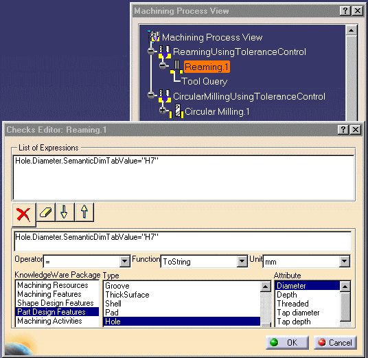
An example of use of Hole Quality in checks is shown below.
- Select File > Open and select the
MPWithToleranceControl.CATProcessdocument.
- Select Machining Process View
 .
.
- Right click the Reaming operation and select Edit Checks.
- Enter the expression in the Checks Editor as shown below and click
OK.
Note that you must select the Diameter attribute before entering the SemanticDimTabValue="H7" string.
An example of use of Tolerance values for a Tool query is shown below.
- Select File > Open and select the
MPWithToleranceControl.CATProcessdocument.
- Select Machining Process View
 .
.
- Right click the Reaming operation's Tool Query and select Definition.
- Enter the expression in the Tool Query Definition dialog box as shown
below and click OK.
Note that you must select the Diameter attribute before entering the ToleranceMin or ToleranceMax string.
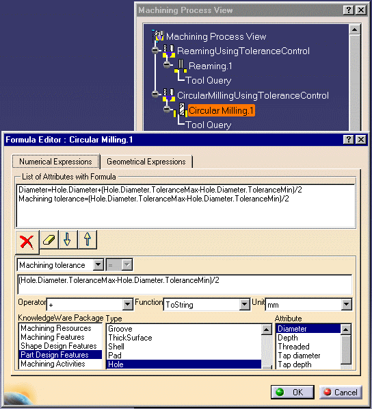
An example of use of Tolerance values in formulas is shown below.
- Select File > Open and select the
MPWithToleranceControl.CATProcessdocument.
- Select Machining Process View
 .
.
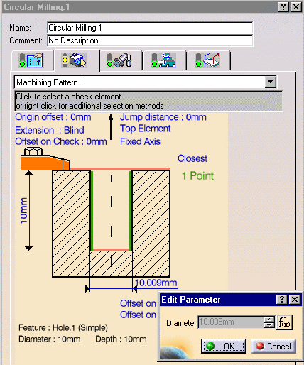
- Right click the Circular Milling operation and select Edit Formula.
- Enter the expression in the Formula Editor as shown below and click
OK.
Note that you must select the Diameter attribute before entering the ToleranceMin or ToleranceMax string.
See Create a Machining Process for more information.
../startup/Manufacturing/Processes/MP_demo.catalog).See Organize Machining Processes for more information.
See Apply a Machining Process for more information.
Click the f(x) button to display the Formula Editor.
Click the f(x) button to display the Formula Editor.
![]()
