 |
This task shows how to apply a
machining process to selected geometry. |
 |
Open
the desired CATPart document, then select a Machining workbench from the
Start menu.
The machining process application uses a standard mechanism of
instantiation of features from a feature reference. In this case, the
feature reference is the machining process to be applied.
When you apply a machining process, the following steps are executed for
each operation:
- Default mapping execution in case of geometry selection
- Checks execution
- Tool query execution
- Cutting conditions execution
- Formula solving.
|
 |
1. |
Select
Open Catalog
 .
Use the Catalog Browser to open the catalogAxialMP1.catalog you created in
the previous task. .
Use the Catalog Browser to open the catalogAxialMP1.catalog you created in
the previous task. |
|
2. |
Double-click the AxialMachiningProcesses
component family. 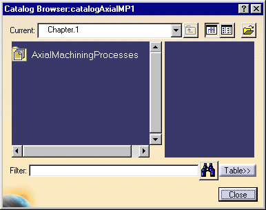
|
|
3. |
Double-click the machining process to be
applied: AxialMachProcess1.
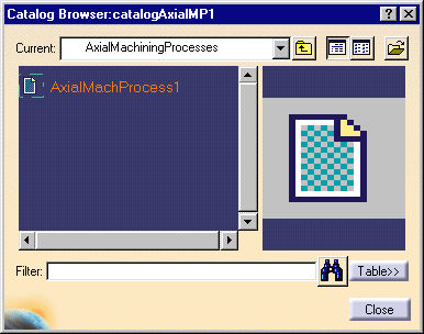
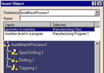
The Insert Object dialog box appears
allowing you to apply the machining
process.
Two input types
can be defined:
-
Geometry
to machine.
The default Geometry
to machine is the
Manufacturing View.
If this is not redefined by selecting
feature
geometry, then only NC data of the
machining process can be processed. In this case if geometry
is referenced
in checks, tool queries or formula,
an error message is issued.
-
Insertion
level in a program.
The program input only appears if
Insertion
level in a program is activated. If no operation is yet inserted
and only one Manufacturing Program is created, then that Manufacturing
Program is the default program input.
Note that for
drilling machining processes, if any
selected
design feature or geometry is linked
to a design pattern, this pattern is taken as selected geometry. |
|
4. |
Select the geometry to be machined. This may
be either a design feature or a machining pattern. |
| |
|
Selecting a design feature
|
|
|
Note that the design feature can be a design
hole or a hole pattern.
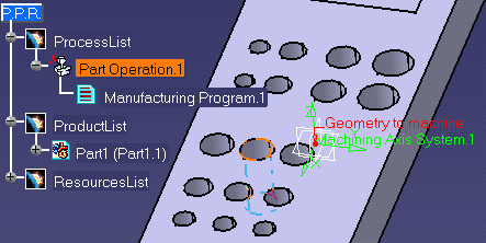
The design geometry is added on the machining pattern
referenced by the machining operation.
Note that all the parameters (such as Jump Distance, Tool
axis strategy, Projection mode, and Ordering mode) defined on the machining
pattern at machining process creation time are kept. |
| |
|
Selecting a machining pattern
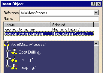
The selected machining pattern replaces the one defined on the operation
at machining process creation time.
Note that the parameters of the selected machining pattern are taken
into account. They replace the parameters (such as Jump Distance, Tool axis
strategy, Projection mode, and Ordering mode) defined on the machining
pattern referenced by the operation at machining process creation time.
The selected machining pattern is shared by all machining operations
created in the program by the application of the machining process. |
| |
5. |
Click OK in the Insert Object dialog box. |
|
6. |
The program is updated with the operations
contained in the machining process:
- Spot Drilling
- Drilling
- Tapping.
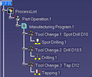
These operations reference the selected geometry and make use of the
formula and checks defined in the machining process.
In addition, the tool queries are resolved so that each operation
references the desired tool. |
|
 |