 |
This task shows how
to complete the setup requirements for creating an isometric drawing from a
3-D document. |

|
It is recommended
that you obtain Alias I-Run V3. The setup process is greatly shortened if
you use V3 instead of V2, and you do not need to install Microsoft VC++ 6.0
compiler. The setup process using both versions is given below.
This procedure only works on the Windows platform.
Version 2
You must install certain third party software for this procedure to
work. These are Alias I-Run V2, Microsoft VC++ 6.0 compiler and two files
from Alias I-Run that may only be available if you have a developer's
license.
The objective of this setup is to ensure that all applications have
access to correct directory paths so that they can work with each other.
When you are done with setup you will have generated a file that acts as
interface between Piping Design and the third party software, and you will
have created certain directories that are needed to create and store the
isometric drawings.
If necessary, you can also use three design rules table to map terms
used in this application to terms used in Alias I-Run. The function also
uses the Bolting design table to obtain certain values. See
Rules Overview
to find out which tables to use. |
|
1. |
Install the third party software
mentioned above. Check to see if the following two Alias files have
installed: pisogen.lib; encrypt.lib. If they have not installed
then obtain them and install them in the following directory:
...Alias I-Run
2.0/Development. |
|
 |
2. |
Using any text editor open the
file CATIALinkIso.bat, which is in the following directory: ...intel_a\code\command.
There are two fields which you may need to edit. For the entry ISOGEN_DIR =
enter the location where I-Run is installed, including the drive letter.
For the entry DEV_STUDIO_DIR = enter the location where Visual C++ is
installed. |
|
3. |
In a command prompt window change
directories to... intel_a\code\command,
enter CATIALinkIso and hit enter. |
|
4. |
When the file has stopped
executing it will have created the file CATIAPcf2Dxf.exe. Move
this file from the intel_a\code\command
directory to the intel_a\code\bin
directory. This file creates the interface between Piping Design and the
third party software. |
|
5. |
Open the I-Run Project Manager: Programs -
Alias Isometrics - I-Run V2 - Project Manager.

You need to create three directories that will be used when generating
isometric drawings. The process will be mentioned briefly here because full
documentation for using I-Run is provided by Alias and should have been
loaded along with the application. |
|
6. |
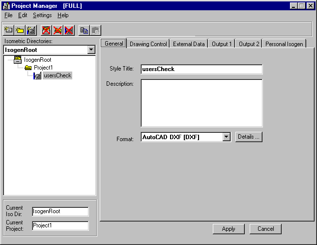
Click the Create New Isometric
Directory button on the Project Manager. A dialog box will display in which
you can enter the name and location of a directory. Click Create Directory
and then OK and the directory will be created. It will display in the
Project Manager - in this example it is IsogenRoot. |
|
7. |
Select the directory you just
created (in this example IsogenRoot) and click the Create New Project
Directory button. A dialog box will display in which you can enter a
directory name. Click OK to create the directory (Project1 in this
example). |
|
8. |
Select the directory you just
created and click the Create New Style Directory button. This directory is
used for user-defined configuration of drawings. Under Template Styles
select a template. Some templates are not intended for DXF-type files
and you will not be able to generate a drawing if you select a template for
any other file format. Read I-Run documentation for the correct
templates. You can modify the template after you have selected it. Enter a
name for the directory and click OK. The directory will be created. |
| |
9. |
From the the menu bar in the Piping Design
workbench, select Tools - Options and the
Options dialog box displays. From the Options dialog box, select Equipment and
Systems - Piping Discipline - Piping
Design and the ISOGen Setup tab displays.
If you are doing this for the first time, there will be no entries in
the Root, Project and Style directory
fields.
You do not have to enter
anything in the first two fields. In the Style field, navigate to the directory you just created. You must not enter anything in the field
I-Run.exe path. The field Error File lists the name and location
of the file where errors in generating drawings are noted.

For Units, select how the units are to display (inches or
milligrams, pounds or kilograms for
Weight) in the 2-D drawing that
will be generated. |
|
10. |
Version 3
Install Alias I-Run V3.
From the the menu bar in the Piping Design
workbench, select Tools - Options and the
Options dialog box displays.
From the Options dialog box, select Equipment and
Systems - Piping Discipline - Piping
Design and the ISOGen Setup tab displays.
If you are doing this for the first time, there will be no entries in
the Root, Project and Style directory
fields.
Enter the full path where the I-Run executable is located in the
field
I-Run.exe path.
The default installation for Alias is: Program Files\Alias\I-Run
v3\I-Run.exe.
Follow Steps 6 to 9 above. |
|
 |
![]()


![]()