|
-
Click Create Rectangle Area Light
 to create an area light source with a rectangular shape, just as a
rectangular spot light would do:
to create an area light source with a rectangular shape, just as a
rectangular spot light would do:
 |
 |
| Note that the
representation of the light source displayed above corresponds to
the default representation mode (i.e. "wireframe display"). You
can choose to display the light source in shading mode by
selecting the corresponding option in
Tools > Options > Infrastructure > Photo Studio > Display. |
| You can also click: |
|
|
 |
 |
|
|
 |
 |
|
|
 |
 |
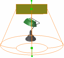
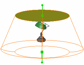
| Each light source is
identified by a specific symbol. To see the light symbol, click
anywhere in the geometry area. |
 |
|
 |
 |
|
Rectangle area light |
Disk area light |
Sphere area light |
Cylinder area light |
|
-
As for ordinary light sources, you can
interactively manipulate area light sources:
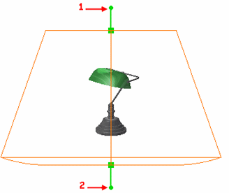 |
- the source point (1)
rotates the surface around its target point
- the target point (2)
rotates the surface around its source point
- the upper green manipulator translates and rotates the
surface around its target point
- the lower green manipulator translates and rotates the
surface around its source point.
|
| Note: this does not apply to punctual area
light sources (i.e. sphere and cylinder) as they have no target
point but only a source point. |
-
Select the
light then Edit > Properties and access the Lighting
tab in order to edit lighting parameters:
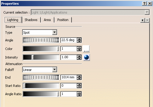 |
 |
The Type
box lets you modify the source type by selecting a new type from
the list: Spot, Point or Directional.
However, changing the source type sets the surface type (under
the Area tab) to "None" in order to avoid
inconsistencies. |
-
Use the slider to modify the color intensity, then
click the
 button if you want to choose another color (the default color is
white). Refer to Defining
a Light Source for detailed information.
button if you want to choose another color (the default color is
white). Refer to Defining
a Light Source for detailed information.
-
Define the light area Angle, the attenuation
End as well as the attenuation Start Ratio and
Angle Ratio. Refer to
Defining a Light Source
for detailed information.
-
Use the Falloff box to define the light
energy attenuation. Refer to
Defining a Light Source.
-
Access the Shadows tab then select the
Ray Traced check box to enable shadow casting. When cleared,
shadows are not calculated for this light source.
| Note: this option is used for rendering
purpose only. |
-
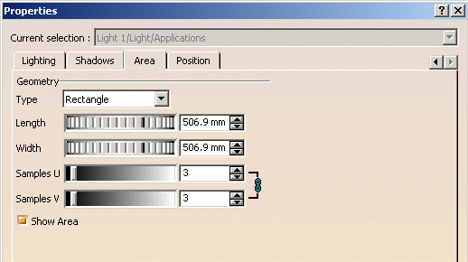
Access
the Area tab:
-
Indicate the light area dimensions in the appropriate
boxes, Length and Width in our example. You can
either use the slider or enter the value directly in the field.
 |
The Type
box lets you modify the surface type without using icons
displayed in the Scene Editor toolbar. The other boxes
are then modified accordingly. For instance, choosing a
Sphere area replaces the Width, Length
and Angle boxes with the Radius box.
In addition to that, the source type (in the Lighting
tab) is also modified to match the new surface type. |
-
The Samples U, V boxes let you define the
rendering sampling precision along the U and V axes. It is thus
relevant for rendering purposes only.
|
The lighting is computed according to the number
of samples defined along the U and V axes: the more light
sources, the less grainy the lighting. However, there is a price
to pay in performance when defining a great number of samples.
The maximum number of samples you can enter is
40, the optimum value being comprised between 7 and 10. |
|
|
Once area light sources have been created, you can select or
clear the Show Area check box to show/hide the
selected light source when rendering the object. Note that the
surface representation of a deactivated light source is also
hidden in the geometry. |
-
Click the Position tab to define the light
source anchoring point and the point to which the source is directed,
respectively in the Origin and Target areas.
| You can define this position in millimeters along
the X, Y and Z axes. |
| As far as Sphere and Cylinder
area light sources are concerned, you just have to define the
origin. |
-
Use the Reference Axis area to define the light source
position relative to the Model axis or to the Viewpoint. Refer to
Defining a Light
source for more information.
-
Click OK to
validate your parameters.
|