-
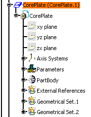
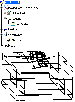
Open the MoldProduct.CATProduct from the samples/Rule/MoldBase directory. In the specification tree, you see the Mold (Mold.1) and the MoldedPart (MoldedPart). In MoldedPart, under Publications you find the published CoreSurface, i.e. the parting surface between core and cavity. If you expand CorePlate, you will see ExternalReferences that enables the synchronization with the molded part.
-
We are going to insert an ejector and activate a rule that will manage the guiding height of the ejector in respect of its position and of the CoreSurface shape.
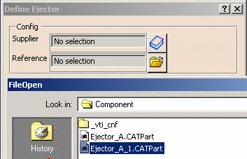
Click the Add Ejector icon . Click the File Open
icon in the dialog box. In the File Open box, browse the
samples directories and select Ejector_A_1.CATPart in the
samples/Rule/Component directory.
-
Select the top face of EjectorPlateB.
-
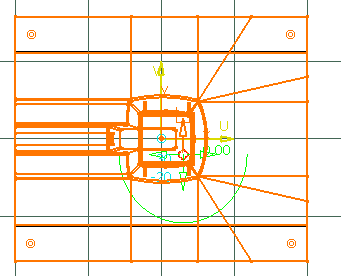
The sketcher is displayed, with a manipulator to position the ejector:
-
The Drill from field is updated with EjectorPlateB. Still in the sketcher, select CorePlate as To.
-
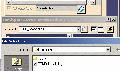
Go to the Parameters tab. Click the rule catalog icon and select the MTDRule.catalog in the samples/Rule/Component directory.
-
In the following dialog boxes, double-click OffsetParting then RuleForOffsetParting. Click OK.
-
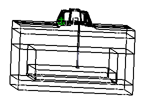
Make sure the Activate Rule check box is selected. Click OK. The ejector is created. Whatever its location, the height of of the guiding hole has always the same value, defined by the parameter named Offset_Parting.
-
Select Edit Ejector component in the contextual menu of Ejector_A_1_1.1
-
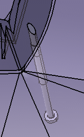
Change the position of the ejector and click OK. Update your model if necessary. You see that the height of the guiding hole is split according to its position and the CoreSurface shape, and has always the same value.
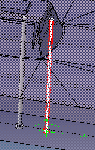
You see the preview of the new split
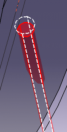
Result
![]()