In this exercise you will create and position an ejector pin onto the current mold base.
-
Click Add Ejector Pin
 .
. -
In the catalog browser dialog box, select the Hasco supplier and
continue into more detailed definition of the ejector pin as follows:

-
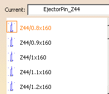
Double-click the reference to display the ejector pin definition dialog box.
As know-how rules are applied, a filter proposes only ejector pins with a consistent length value. -
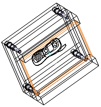
Pick the bottom face on EjectorPlateA as shown below:

-
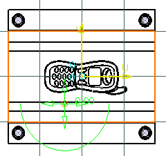
Locate the ejector pin on the grid.
Define the plates to drill in the dialog box from EjectorPlateA to Core Plate.

-
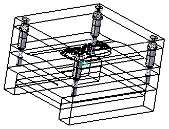
Click OK to validate the creation of the ejector pin. Here is the final result:

![]()