In this exercise you will insert 4 leader pins that
will be positioned on already existing points.
Note that depending on the catalog used, the number of steps until the final
component may be different.
-
Click Add Leader Pin
 .
. -
Click
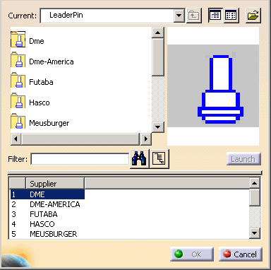
 to open the associated catalogs and select
the Dme supplier:

Continue into detailed definition of the leader pin.
-
Double-click the reference to open the leader pin definition dialog box.
-
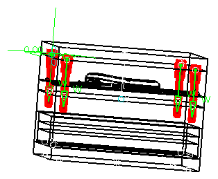
First select a point which is displayed as a circle (and not a cross) on the mold base.
As the point is called LeaderPini (i=1to 4), three other leader pins are automatically positioned on the other points named LeaderPini.
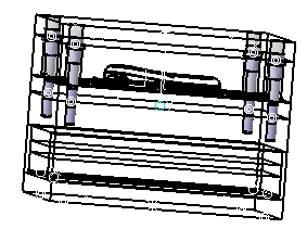
To create the holes associated to each leader pin, position the From and the To elements respectively to ClampingPlate and CavityPlate.
You obtain the following preview:

-
Click OK to complete the creation of the leader pins.

-
If you are not satisfied with one of the created leader pins,
right-click it in the specification tree and select Edit LeaderPin Component or Delete Component.
![]()