Kinematics as used in most cases
-
Open MoldWithMoldedPartAndComponents.CATProduct from the samples/MoldAndPart directory.
Make sure that the product including the molded part and the mold is active in the specification tree.
-
Select the Edit>Links item. In the dialog box, double-click select the mold product to open it.

-
Select Start>Digital Mockup> DMU Kinematics.
-
Click New Mechanism. Click OK to validate the default name for the mechanism.
Click Auto Create.
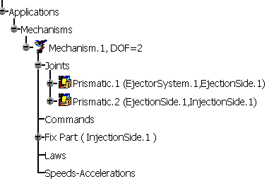
Click OK. Joints are created in the specification tree:
-
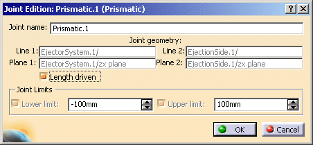
Double-click the joint. Select the Length Driven check box. Repeat the operation on the second joint.
A message indicates that the simulation can be started:
-
Click the simulation icon, and select the newly created mechanism. Moving Command.1 and Command.2 sliders animates the joints.
For more information, refer to DMU Kinematics documentation.
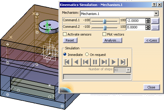
Kinematics with sliders
You will also need to create offset constraints for each slider that will serve to move the slider out of its slot.
-
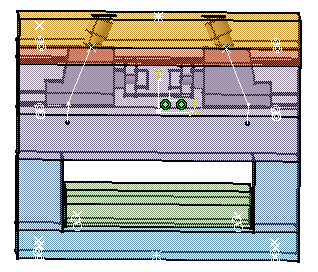
Open file KinematicSlider.CATProduct in the samples/KinematicSlider directory.
-
Select Edit >Links. Then select the mold product in the dialog box. Open it.
-
Switch to DMU Kinematics. Click Assembly Constraints Conversion
 .
.
-
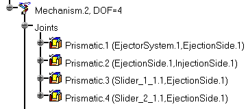
Click New Mechanism , then Auto Create , then OK. Two joints are created in the specification tree:

-
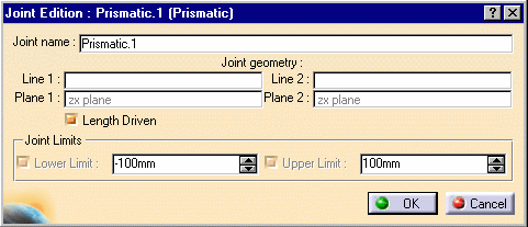
Double-click the joint called Prismatic.1 in the tree. Select the Length Driven check box in the dialog box. Click OK.
-
For the first slider, click Point Curve Joint
 .
.
In the dialog box, select: - the sketch for the movement of the slider as Curve 1,
- the point at the top of the sketch as Point 1.
Select the Length Driven check box.
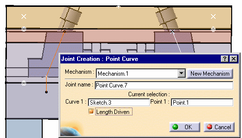
Click OK. -
Repeat step 5 for the other slider. Do not select the Length Driven check box.
A message indicates that the simulation can be started.

![]()