|
This task shows you how to
create coolant channels. You can
create a coolant channel in any plate
in a mold. |
 |
There are several restrictions concerning the
manipulation (notably when copying, pasting, deleting, dragging and
dropping) of components and drilled CATParts. Click
here for more information. |
|
The points used to create
coolant channels can be simple points, vertices at the ends of a line,
projected points or points from a sketch. You can either:
- select one point after the other, or
- select a line in which case the extremities will be used, or
- select a sketch. A coolant channel is created or each element in the
sketch.
|

|
If the elements used to build coolant channels (points,
lines, ...) are created with an external reference, those reference links
are broken at the creation of the coolant channels to avoid any lifecycle
problem. |
 |
-
Open
Split.CATProduct in the samples/Split directory.
-
Double-click CoreCooling (in CoreCooling1).
This opens Part Design.
-
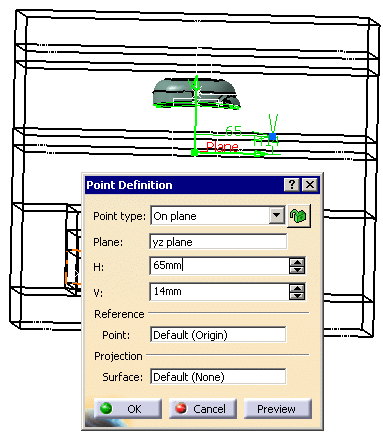
Click the Create a Point icon
 from the Wireframe and Surface application.
-
Select a point from the planes on which are based the core
plate and the cavity plate of the mold.
Click OK to complete the creation of
Point1.
-
Turn the mold round and select a point on one of the four
other planes. Click OK to complete the creation of Point2.
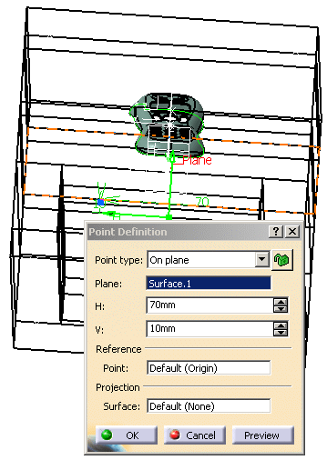
-
Double-click Product1 to come back into the
Mold Tooling Design workbench.
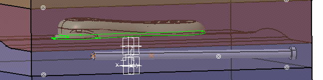
-
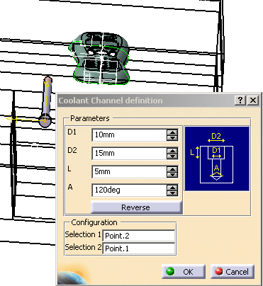
Click Add Coolant channels
 . Select the two points
that you just created because they are going to be the end points of the
coolant channel. The Coolant Channel definition dialog box is
displayed and the coolant channel is previewed.
You may modify any of the parameters you choose
and the modifications are simultaneously previewed. . Select the two points
that you just created because they are going to be the end points of the
coolant channel. The Coolant Channel definition dialog box is
displayed and the coolant channel is previewed.
You may modify any of the parameters you choose
and the modifications are simultaneously previewed.
-
Click OK to create the coolant channel. You may
edit the coolant channel once it has been
created.
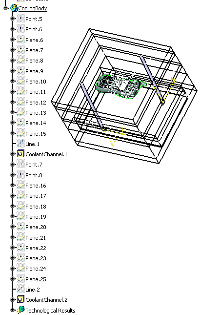
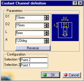
-
A set of parameters define the
geometrical characteristics of the coolant channel, as shown in the dialog
box.
 |
|
Reverse
reverses the first and last points (first becomes last and last
becomes first) when both points belong to the planes that define the
CoreCooling or CavityCooling.
If one of the points does not belong to one of these planes, the
complementary solution is proposed when clicking on the Reverse
option. |
|
| |
| |
|
|
- In creation mode, when neither element (point or end point) used for
creating the coolant channel belongs to the planes that define the
CoreCooling or CavityCooling, the user is proposed two
solutions.
- The reverse option is used to display the complementary solution:
- The Reverse option cannot be used at final completion of
the coolant channel. However for each element of the sketch, the user may
choose the reversed solution by clicking on the following dialog box which
is automatically displayed when required.
- All coolant channels are created simultaneously and share the same
parameters. But they are independent (and are displayed so in the
specification tree) and may be edited individually once the creation is
completed.
- You can also use elements from the sketch but you need to select them
one after another and create the coolant channels individually.
|
| |
-
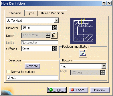
To
edit the channel once it has been
created, you select it in the specification tree using the Coolant
Channel Edition option in the contextual menu or graphically with a
simple click on the object. The parameters that can be changed are the
same as those for channel creation.
-
If you wish to edit parameters other than those required
for channel creation, double-click the coolant channel either in the
viewer or the specification tree. A dialog box is displayed that allows
you to edit the hole properties.
|
| |
Deleting a coolant channel
|
| |
-
Delete a coolant channel by:
- editing CoreCooling or CavityCooling
(depending on where the coolant channel was created)
- selecting the coolant channel you want to delete in the
CoolingBody
- use the contextual menu to delete it.
|
|
|
 |